Embeded Programming
Here are the various sensors and output devices tested on the Arduino UNO microcontroller.
Click on a link below to jump to a section:
- Blink
- Traffic light
- Blink with external interupts
- Analog input with potentiometer
- Servo motor
- Controlling a servo motor with a potentiometer
- Blink while counting button presses
- Passive infrared sensor
- Ultrasonic sensor
- 555 Timer
Blink
This program blinks two light emitting diodes(LEDs) every second.
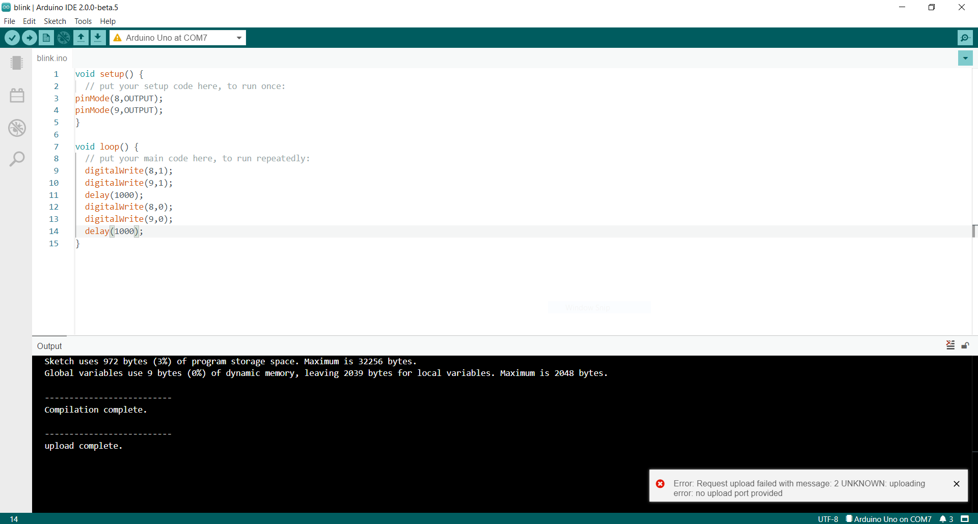
Click here to download code.
Traffic light
This program waits for a button press, then, waits five seconds to turn on the green LED and turn off the red LED.
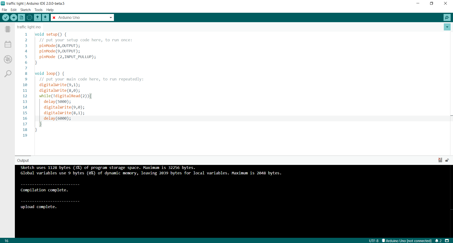
Click here to download code.
Blink with external interupts
This program blinks an led and when the button is pressed the red LED imediately turns off and the green LED turns on. This program uses interupts to interupt the delay.
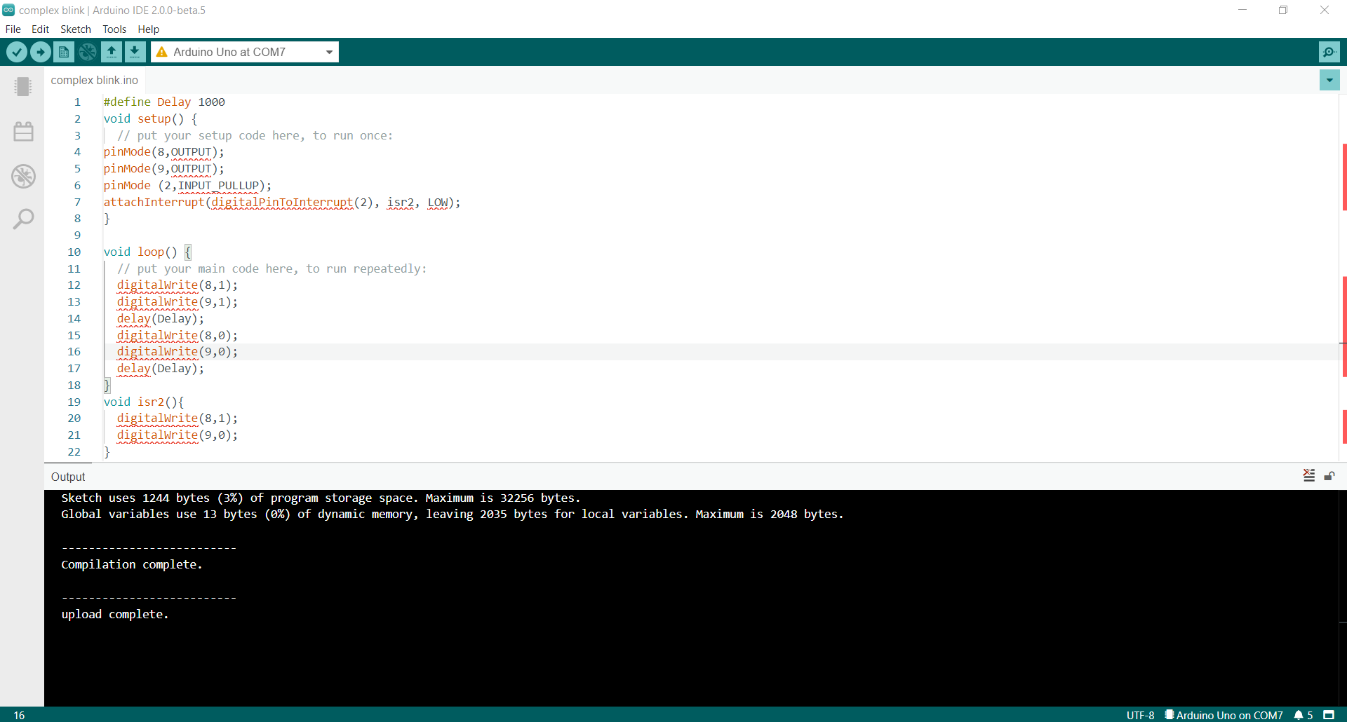
Click here to download code.
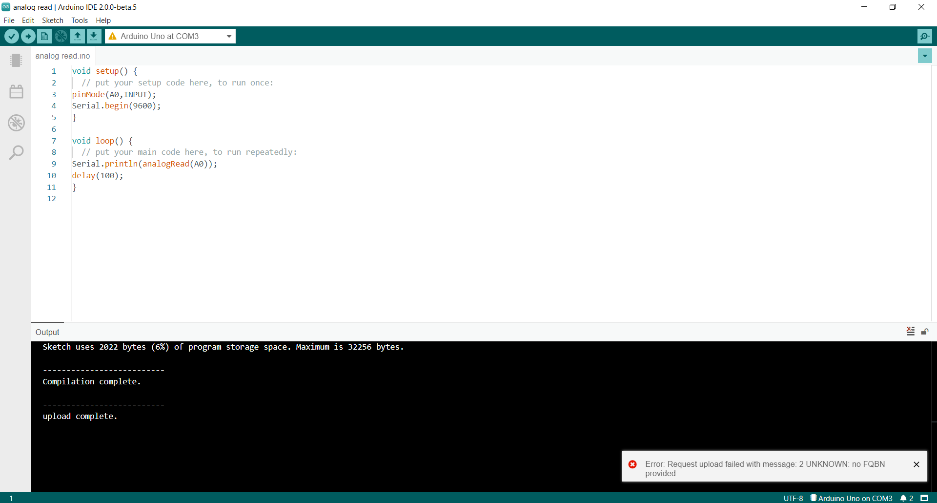
Analog input with potentiometer
This program reads the analog voltage using analogRead() and prints it to the serial monitor. The analog digital converter(ADC) on the ATMEGA328p is a 10 bit successive approximation ADC. The analog voltage is converted to a digital signal one bit at a time atarting from the most significant bit(MSB).
Click here to download code.
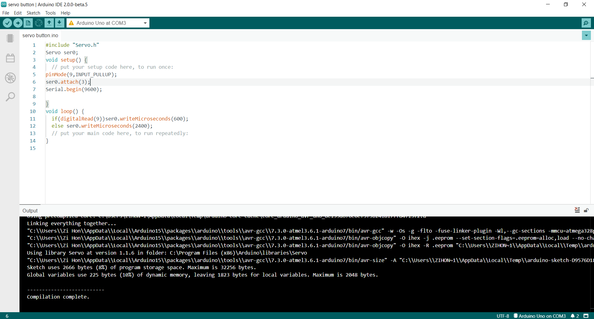
Servo motor
This program reads the state of the button and turns a servo motor.
Click here to download code.
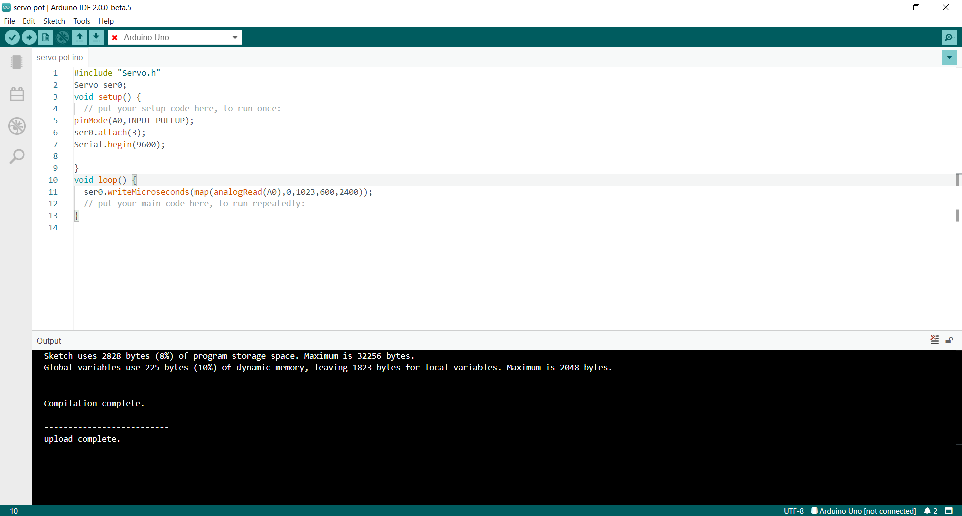
Controlling a servo motor with a potentiometer
This program reads the analog voltage using analogRead() and uses the map()function to map analogread() values to servo PWM values.
Click here to download code.
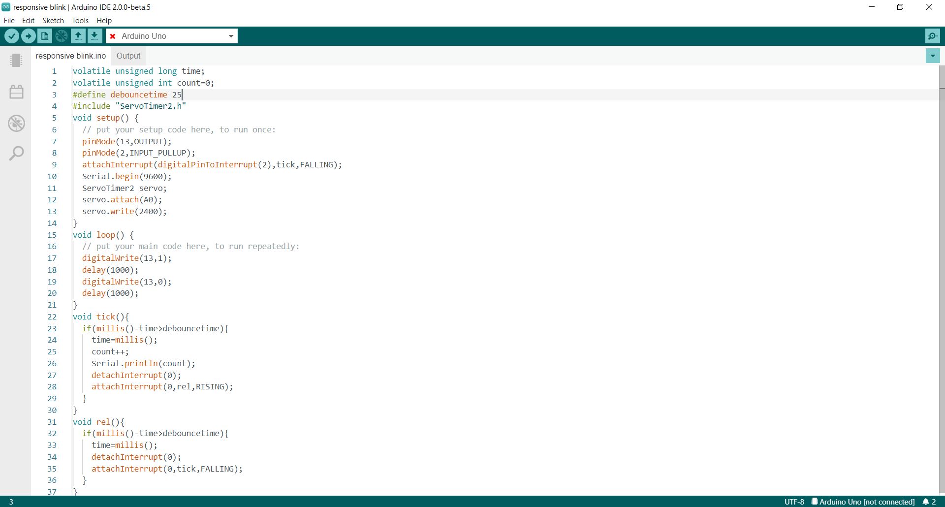
Blink while counting button presses
This program blinks an led and when the button is pressed, the number of presses is printed to the serial monitor. This program uses interupts to interupt the delay of the LED blinks.
Click here to download code.
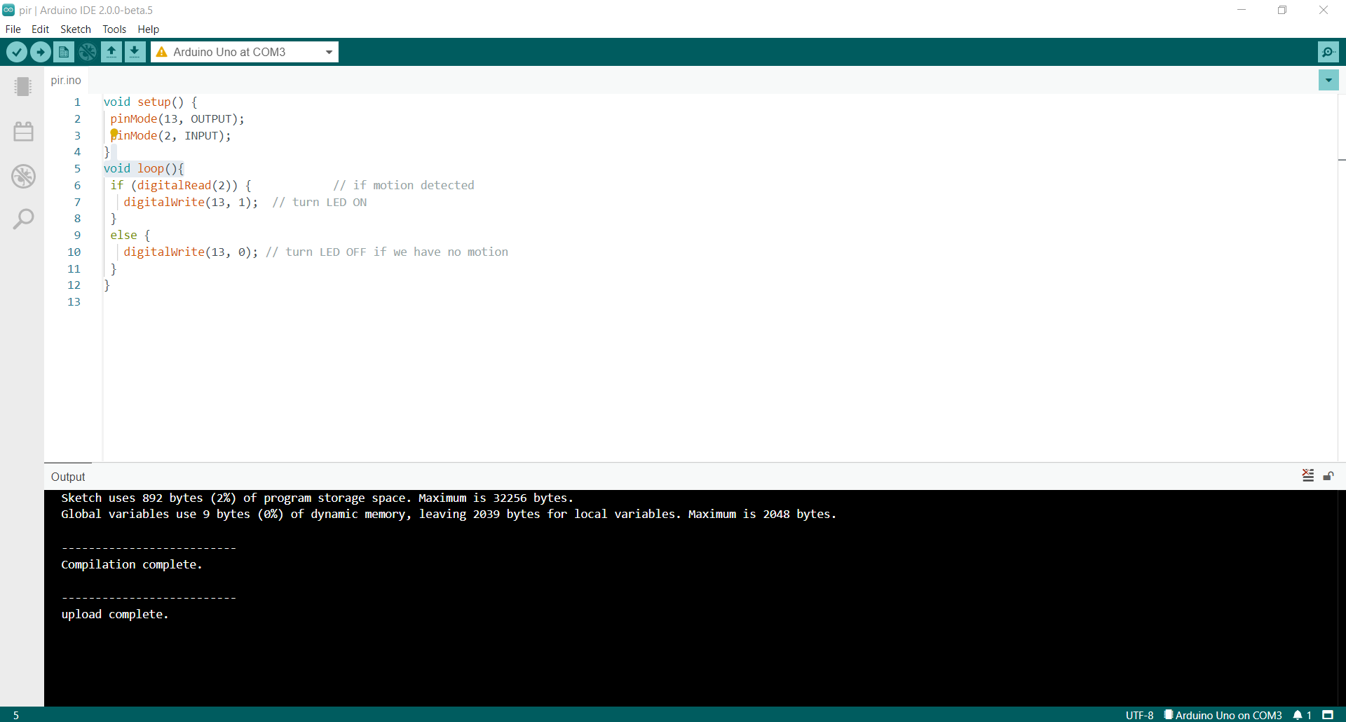
Passive infrared sensor
When motion is detected, the PIR sensor will output a logic high and the microcontroller will turn on the LED.
Click here to download code.
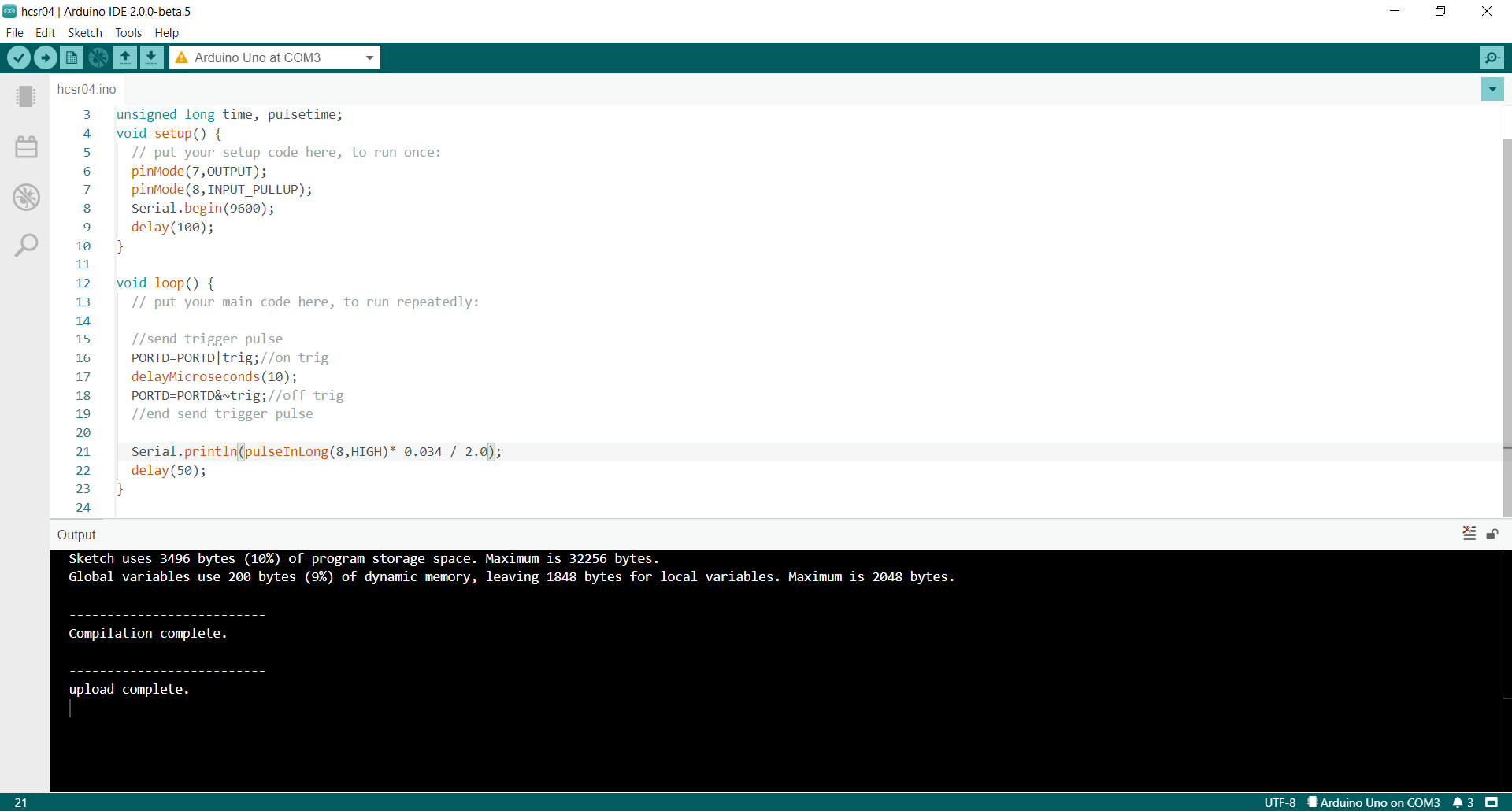
Ultrasonic sensor
The microcontroller sends a pulse to the ultrasonic sensor to initiate the distance measurement. The ultrasonic sensor sends out pulses of sound and wait for their reflection to be received. The period of time between the pulses being sent and received is sent as a pulse to the microcontroller. The microcontroller measures the pulse duration and determines the distance.
Click here to download code.
555 timer
The 555 timer is commonly used as a clock source or as an oscilator. It works by using an RC circuit. An RC circuit, comprises of a resistor and a capcitor. When the 555 timer is used as an astable multivibrator, the capacitor is charged slowly through the resistor, and the voltage across the capacitor slowly increases. A comparator will compare the voltage accross the capacitor and when the voltage reaches a certain point, two thirds of Vcc, the capacitor will be discharged through a resistor until the voltage across the capacitor reaches one third of Vcc.
Click here for more information on the 555 timer.
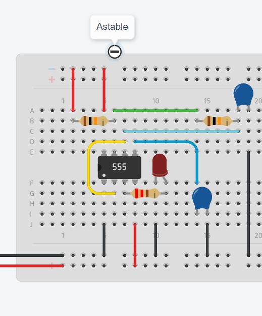
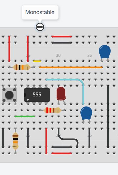
Below shows the Tinkercad simulation of the 555 timer in Astable, Monostable and Bistable mode.
In astable mode, the LED blinks continously. In this mode, the 555 timer can be used as a clock source. The 555 timer can be used to generate a tone for a buzzer or provide a PWM signal to control a motor.
In monostable mode, the LED turns on for a short time after the button is pressed. In this mode the 555 timer can be used to dectect rising and falling edges with additional components.
In bistable mode, when the trigger pin of the 555 timer is connected to ground, the output will be high, when the reset pin is connectd to ground, the output will be low. In this mode the 555 timer acts as a SR latch, with trigger being set. The 555 timer can be used to debounce a switch as multiple pulses on the trigger pin will only cause the output to change once. The 555 timer can also be used as a single bit of memory, a flag for a microcontroller that can be triggered by an external event.
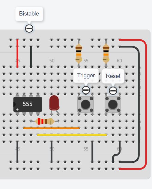
Notice that when trigger or reset is pressed multiple times, the output does not change.
Click here to see the Tinkercad simulation.
555 timer on breadboard
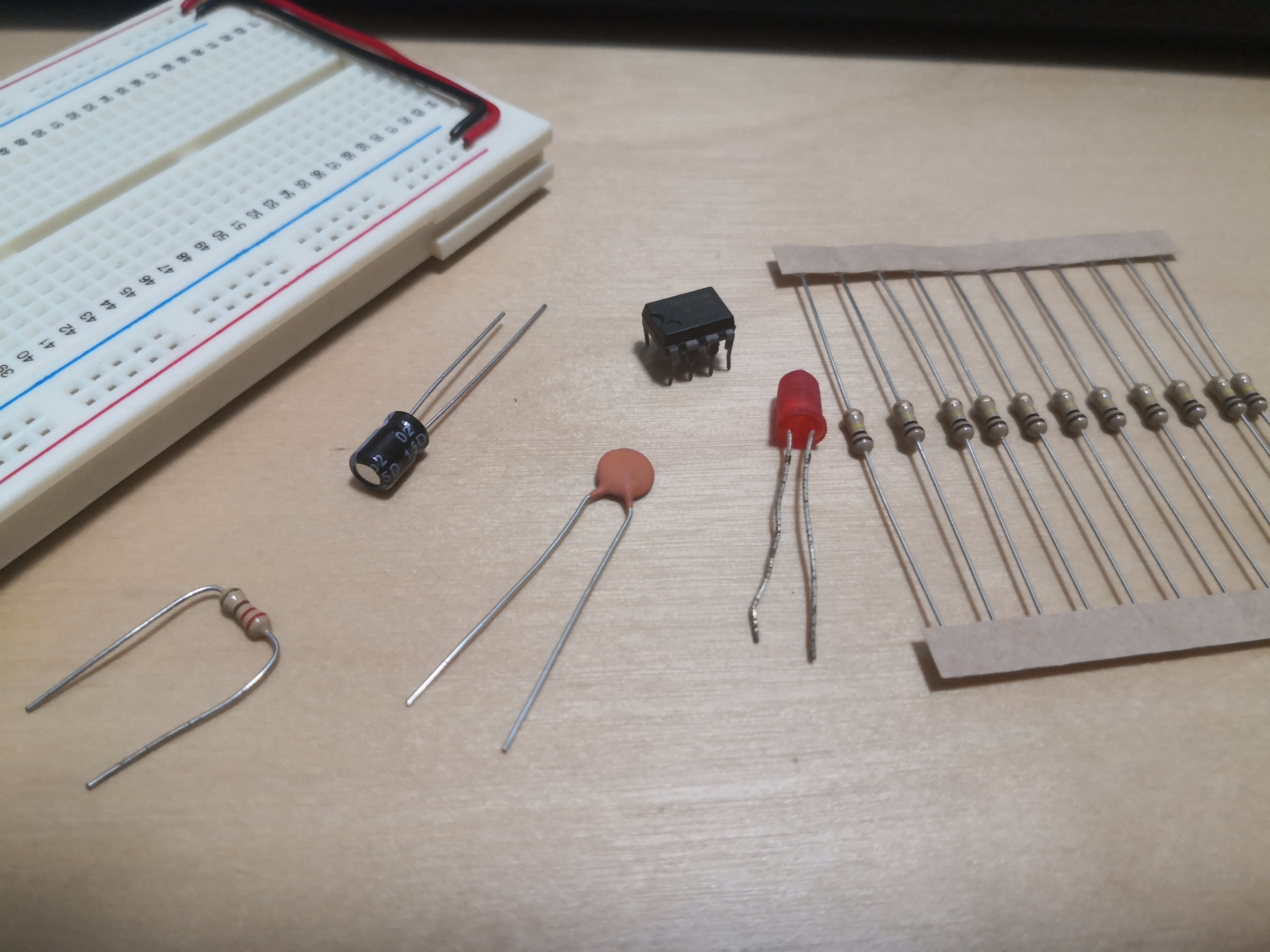
Parts needed for the 555 timer:
| N.O. | Part Description | Qty |
|---|---|---|
| 1 | NE555P | 1 |
| 2 | Breadboard | 1 |
| 3 | 100nF ceramic capacitor | 1 |
| 4 | 100uF aluminium capacitor | 1 |
| 5 | 10K ohm resistor | 2 |
| 6 | 220 ohm resistor | 1 |
| 7 | LED | 1 |
| 8 | Male to male jumper | 7 |
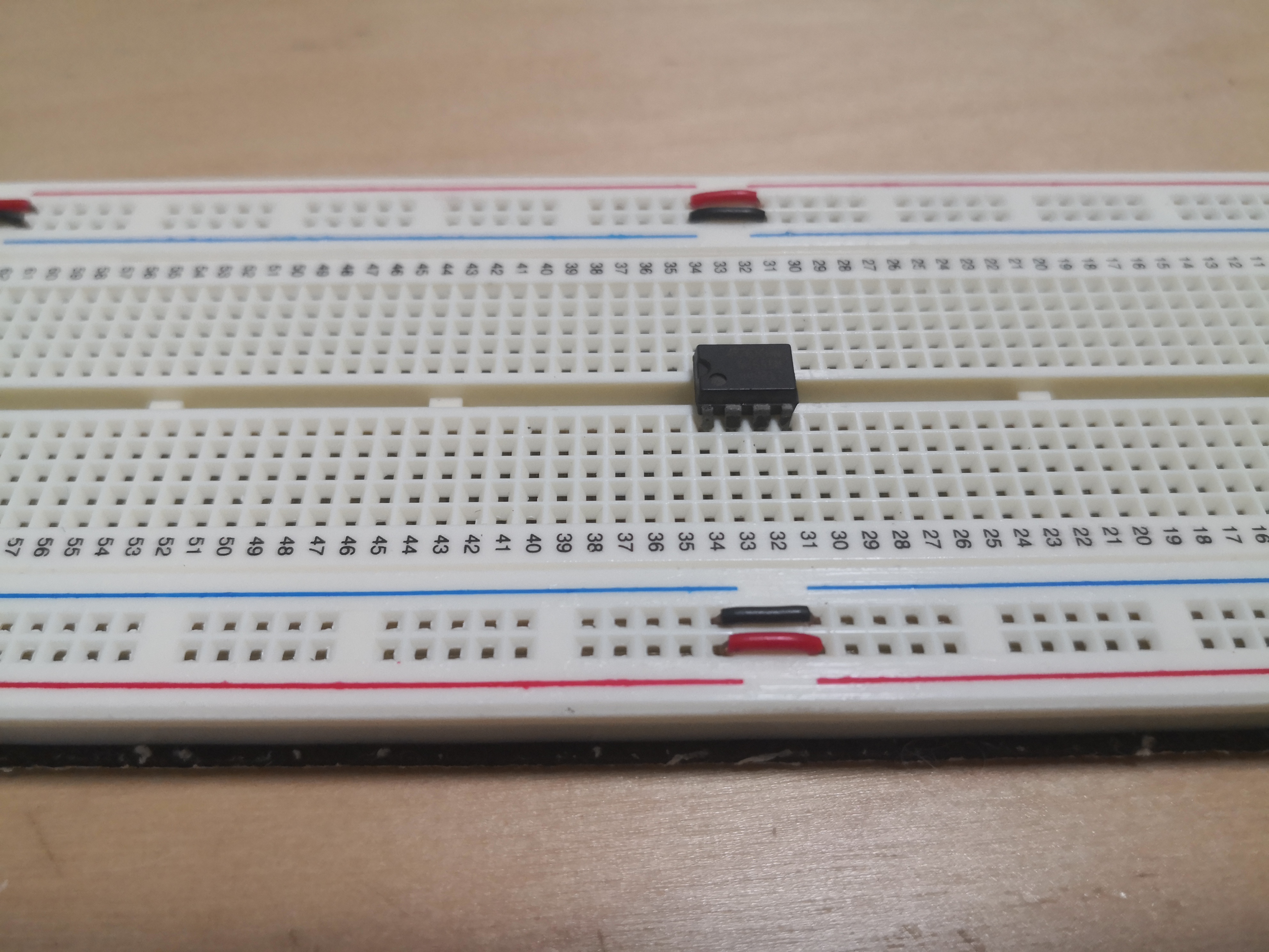
The 555 timer is inserted into the breadboard across the trench.
The 220 ohm resistor and LED are connected to the output of the 555 timer.
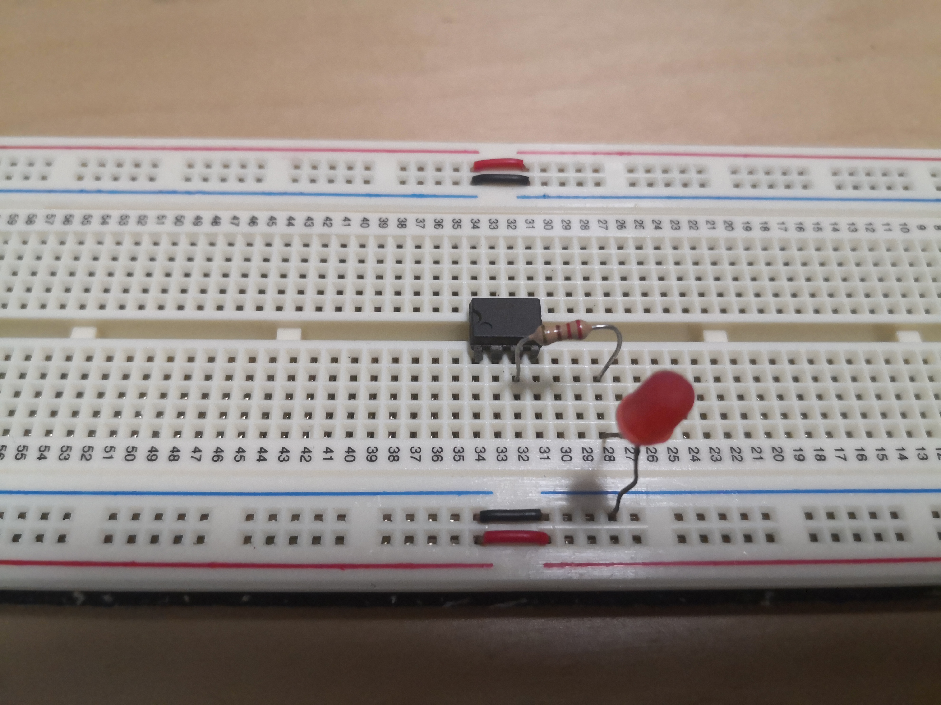
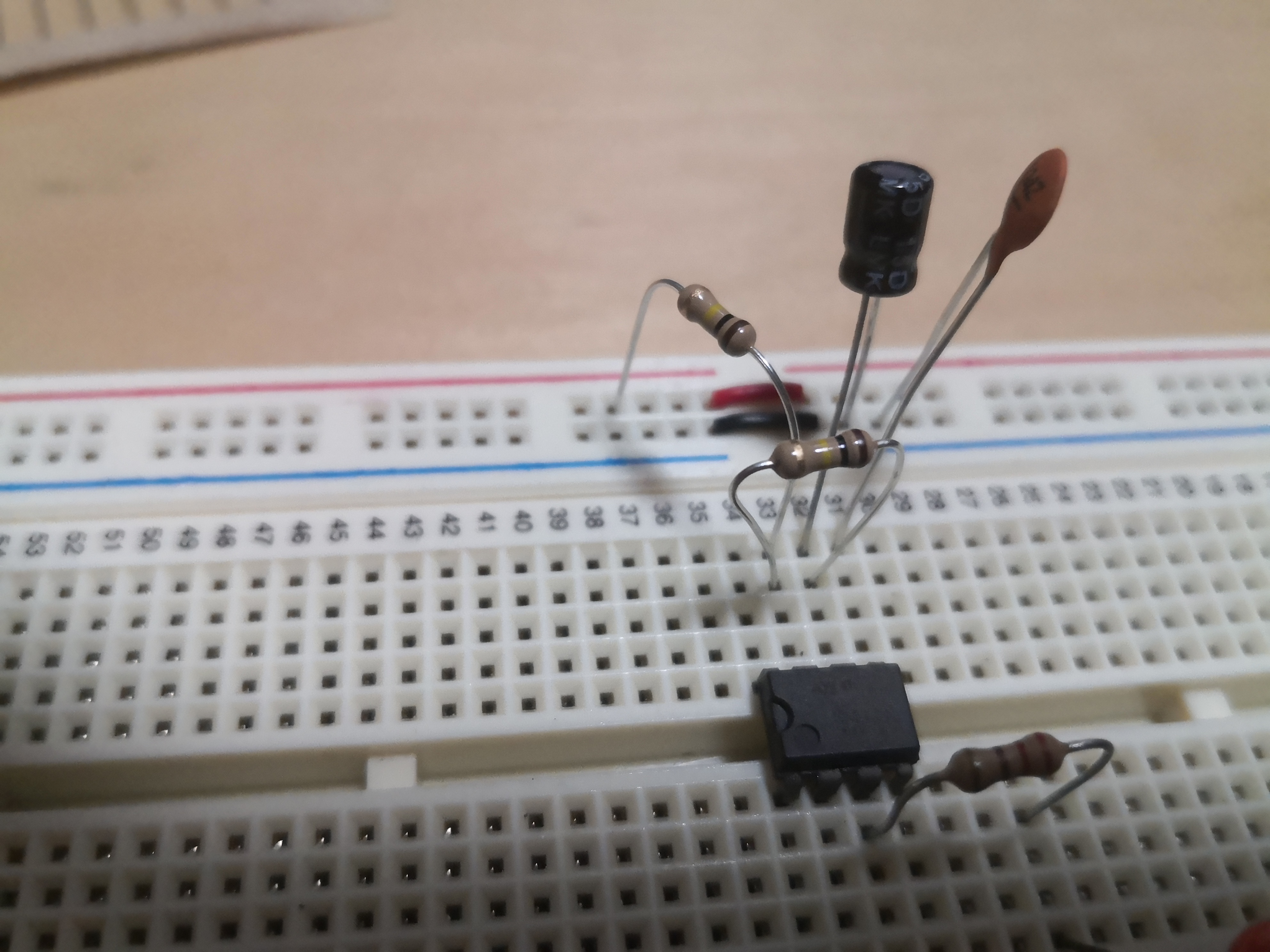
The timing and control capacitor is connected.
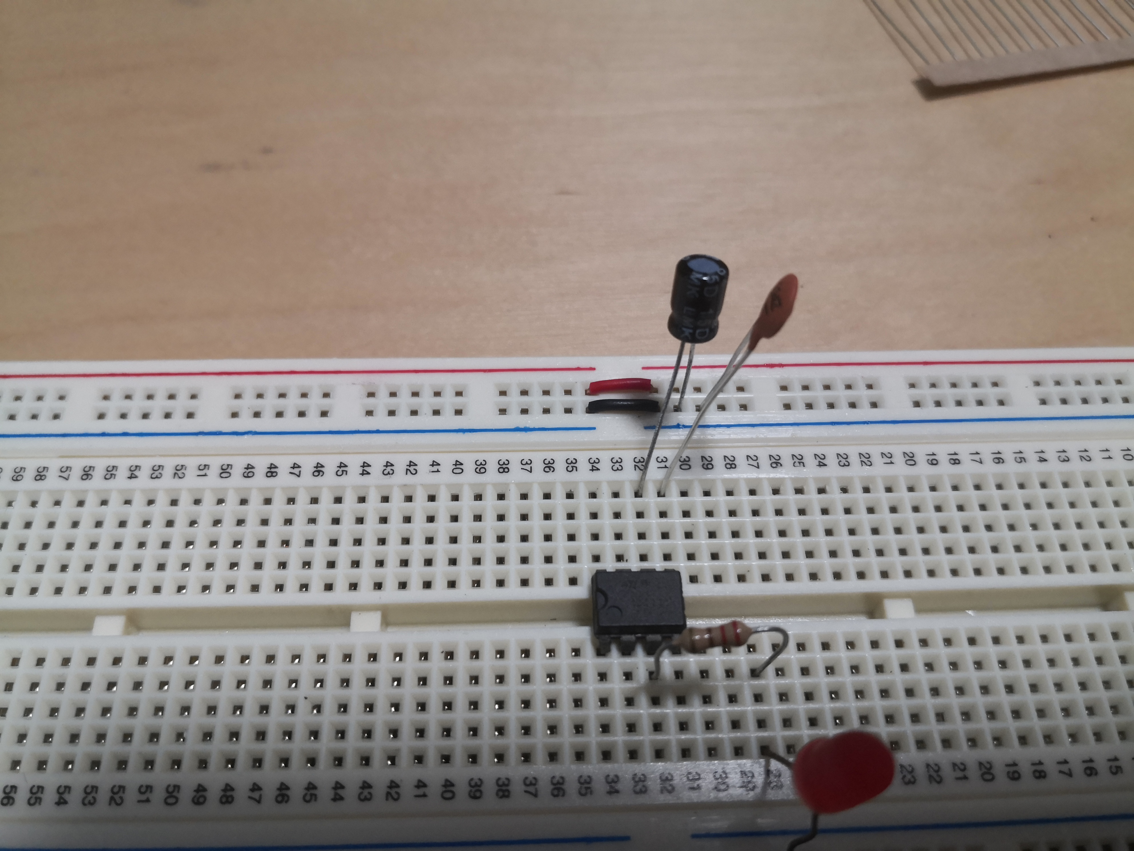
The timing resistors, two 10K ohm resistors are connected.
Jumpers are used for the other connections.
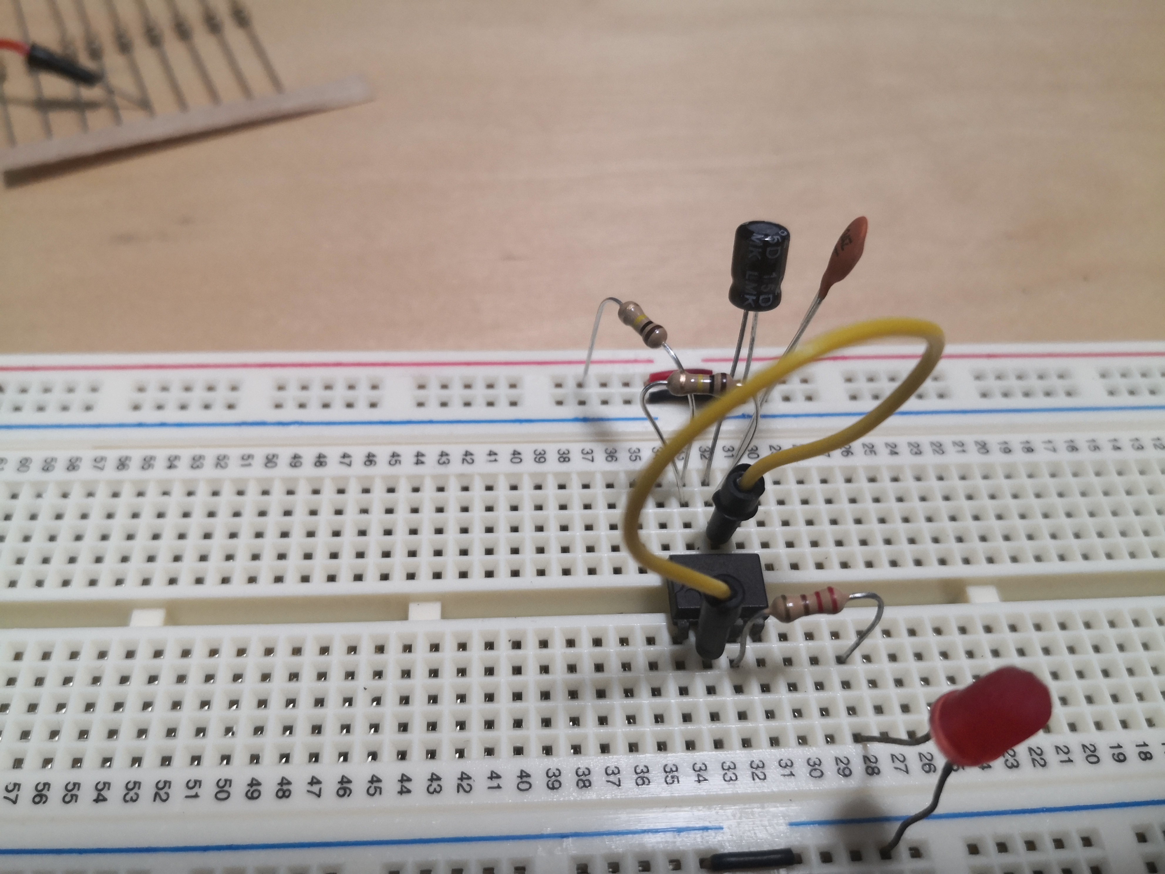
555 timer in astable mode. The two 100K ohm resistors used were switched to 10K ohm resistors so that the LED blinks faster.

LED blinks continously.
555 timer in monostable mode.
Led turns on and stays on for a short time after button is pressed. A jumper is used as a switch.
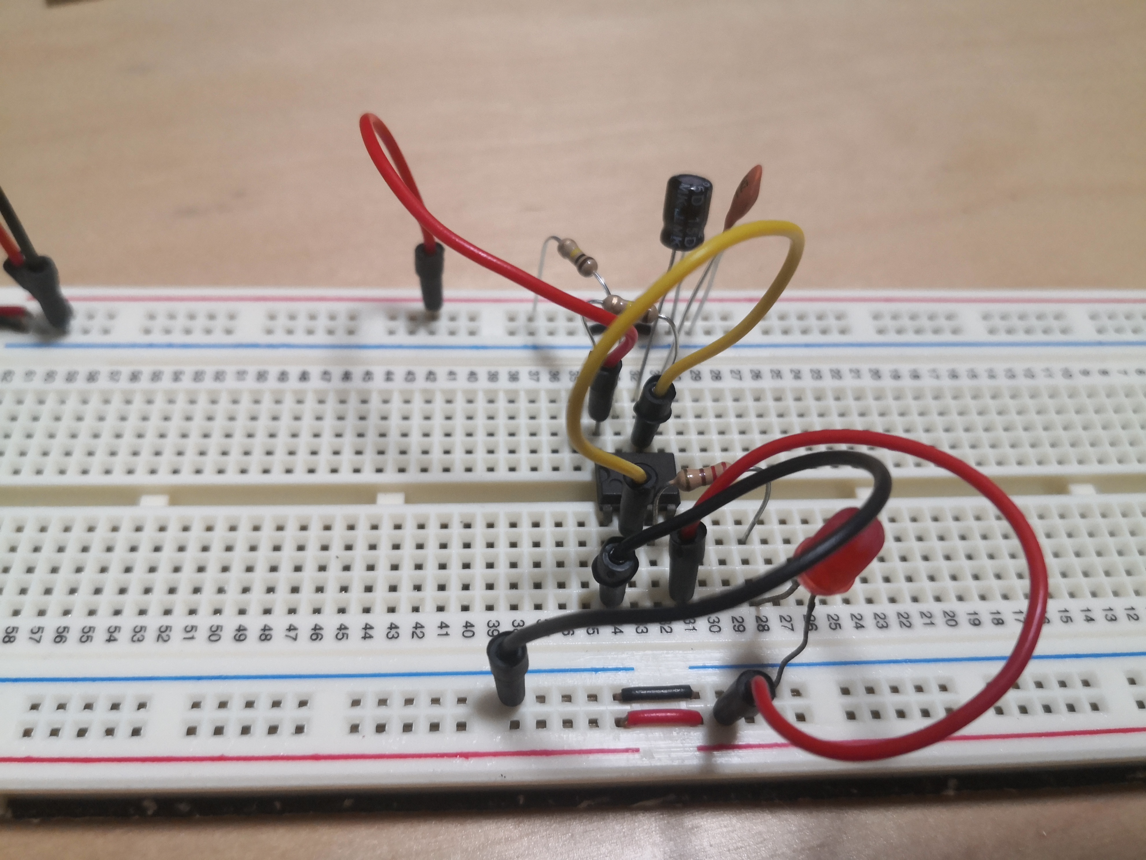
555 timer in bistable mode.
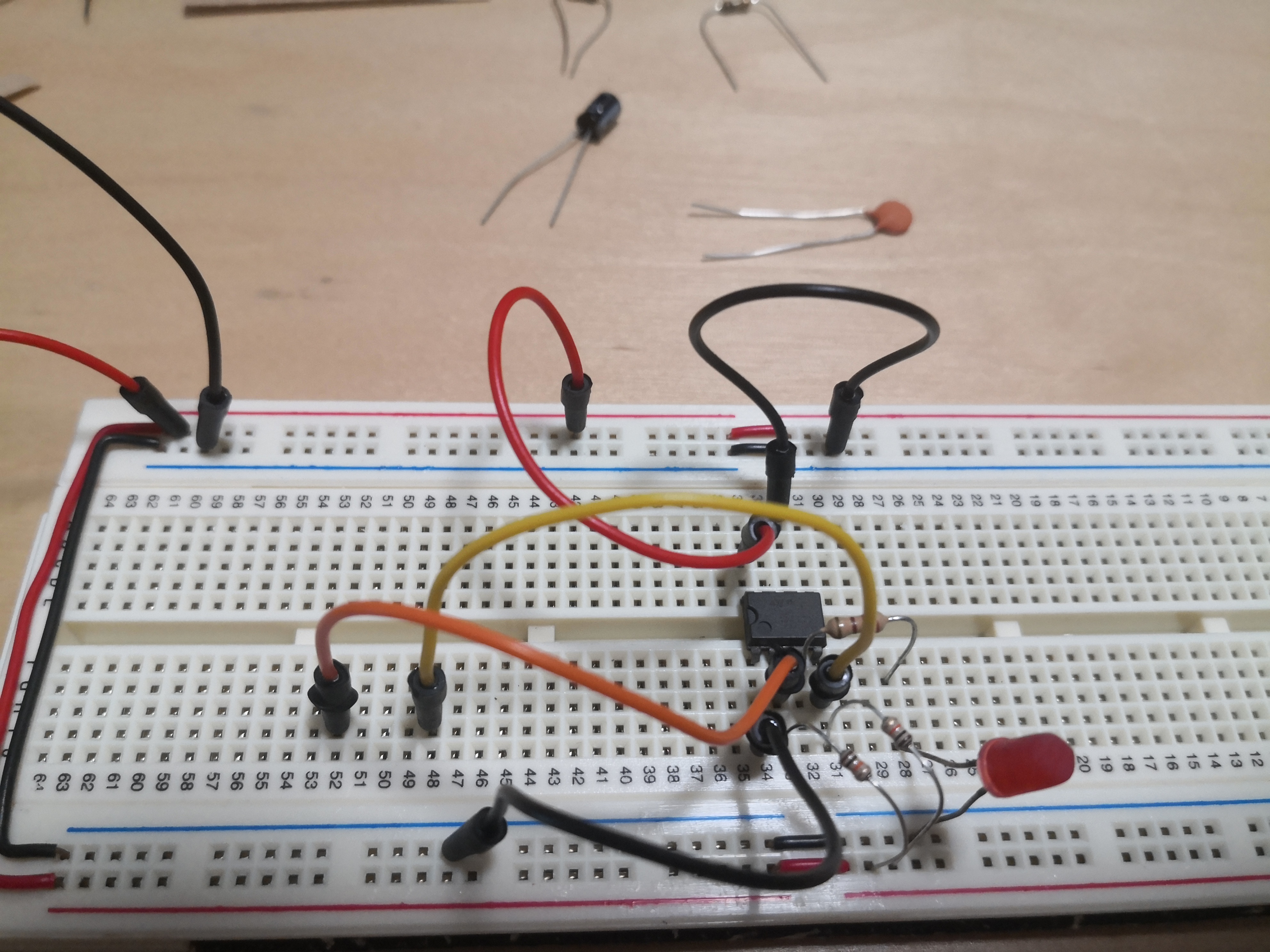
The LED turns on when the trigger(orange) is connected to ground. And turns off when the reset(yellow) is connected to ground.