Final Project
Here lies the documentation of my final project, the pen plotter.
Click on a link below to jump to a section:
- Ideation
- Features
- First prototype-CAD
- First prototype-inverse kinematics
- First prototype-Programming
- First prototype-Electronics
- First prototype-file format
- First prototype-toolpath generation
- First prototype-Testing
- First prototype-problems
- Second prototype-CAD
- Second prototype-inverse kinematics
- Second prototype-problems
- Final prototype-CAD
- Final prototype-BOM
- Final prototype-3D printing
- Final prototype-Laser cutting
- Final prototype-Electronics
- Final prototype-Testing
- Final prototype-slide
- Final prototype-video
- Final prototype-How to use the pen plotter
- Final prototype-Possible improvements
Ideation
There are many types of kinematics systems to choose from when designing. The below are the three kinematic systems considered. The scara robot was chosen as the final design as it was different from the cartesian systems. In addition, it is simpler comapared to the cartesian and the parallel bar because it requires lesser linkages and motion components to function.
Cartesian robot
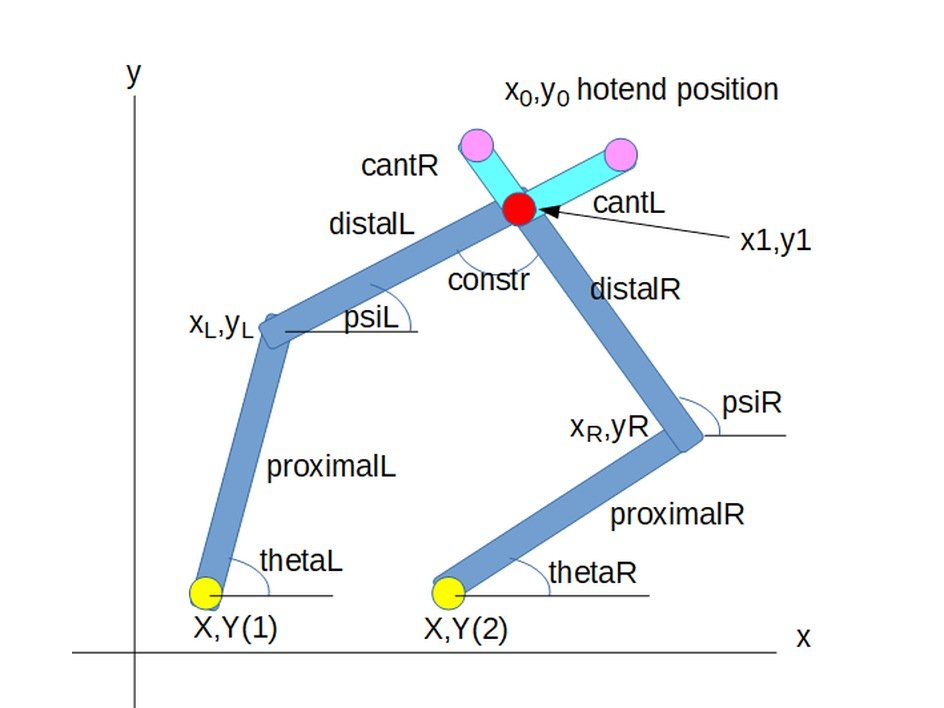
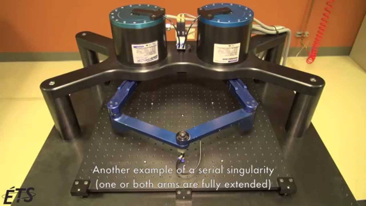
Parallel bar robot
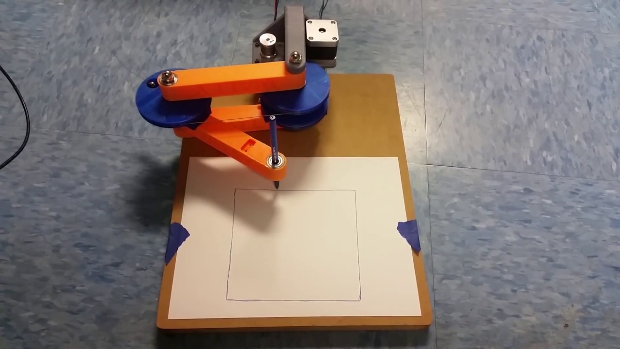
Scara robot
Features
The main features governing the design are:
- Easy toolpath generation-This is acheived using Cura, an easy to use 3D printing slicer.
- Untethered operation-The plotter should not need to be connected to a computer in order to function. Most 3D printers have an option to print from an SD card. The pen plotter should be able to plot from an SD card.
- A6 Working area-Large enough for simple designs, yet small enough to be portable.
- Screen to show avalable toolpaths so that the user can select the toolpath.
First prototype-CAD
The first prototype was a sanity check. To make sure that this concept was even doable by me. As such crucial components such as the end effector, the pen lifter and base were ommited.
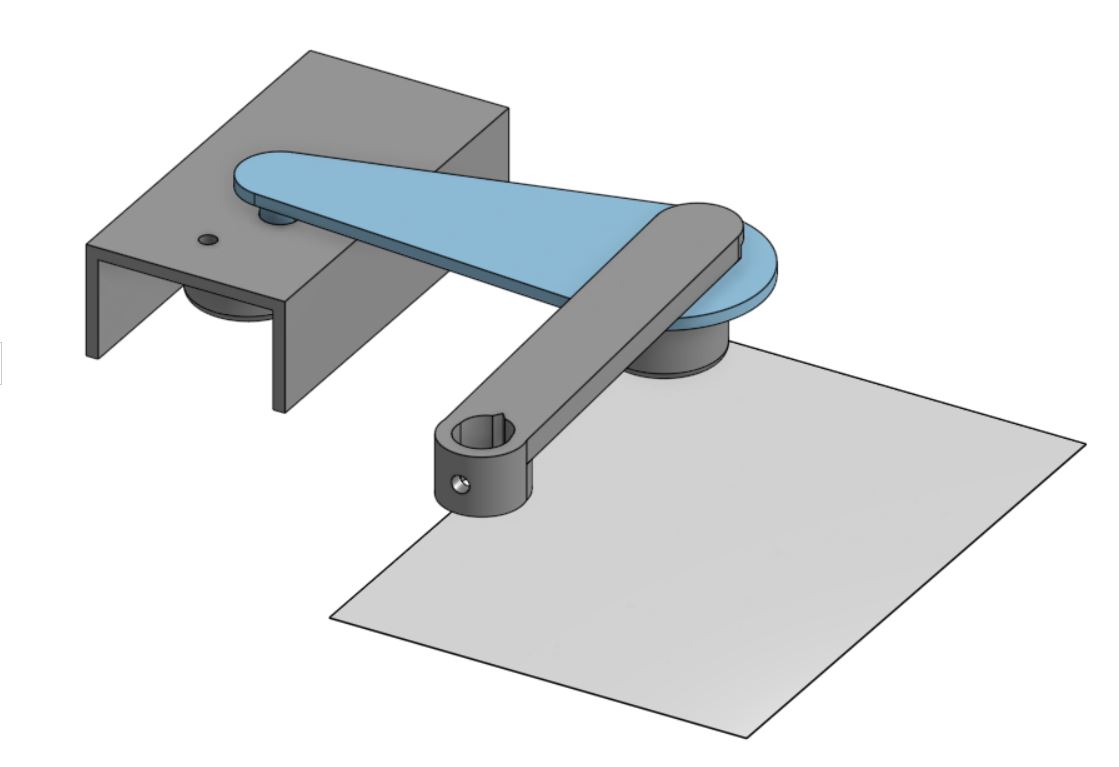
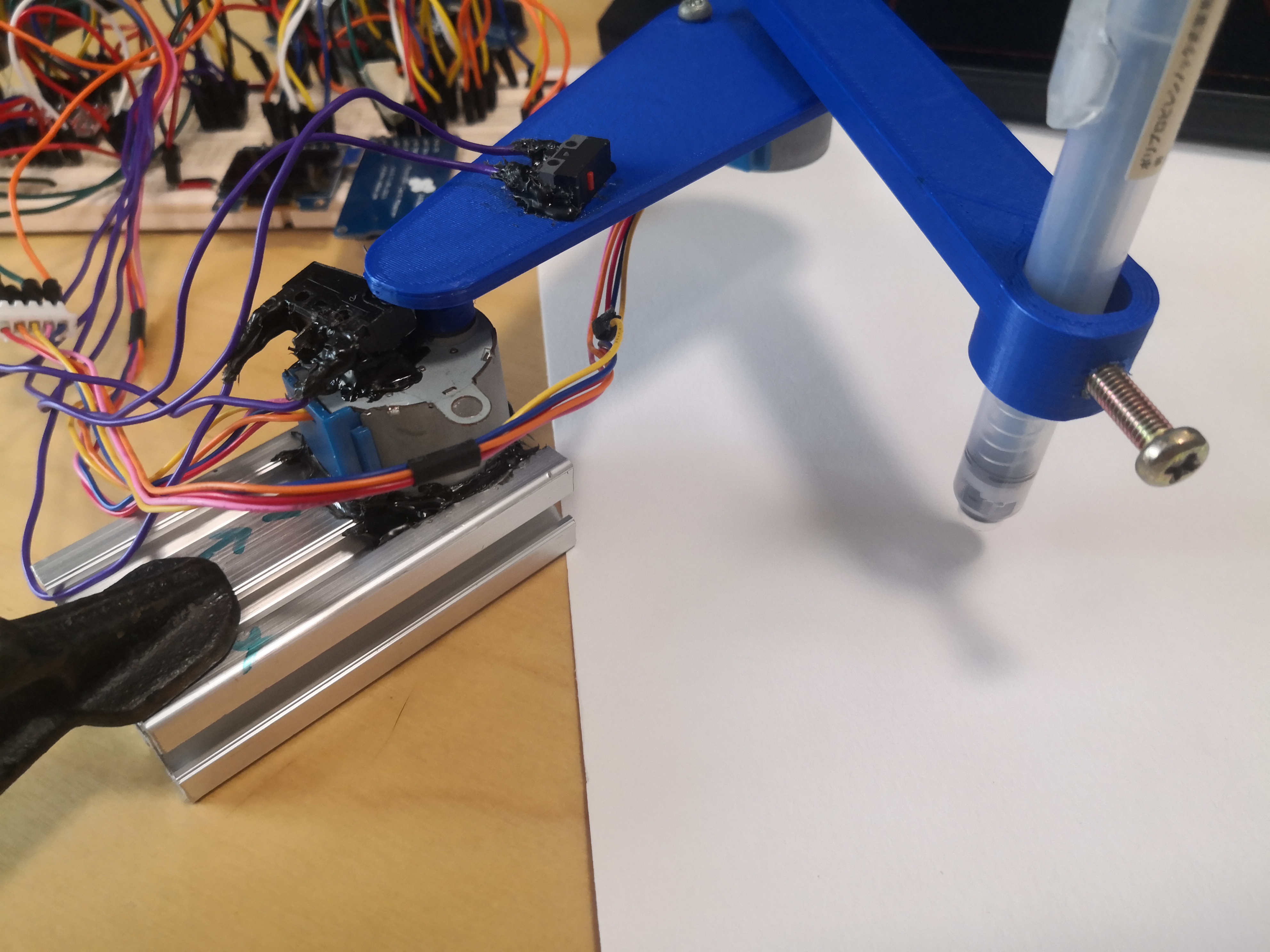
Below is the assembled first prototype.
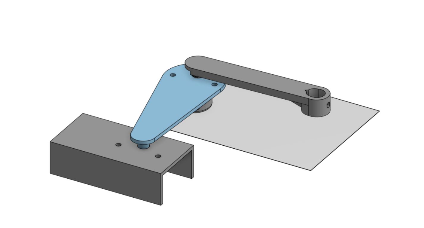
The small stepper motors used are light enough to be extended to drive the second arm.
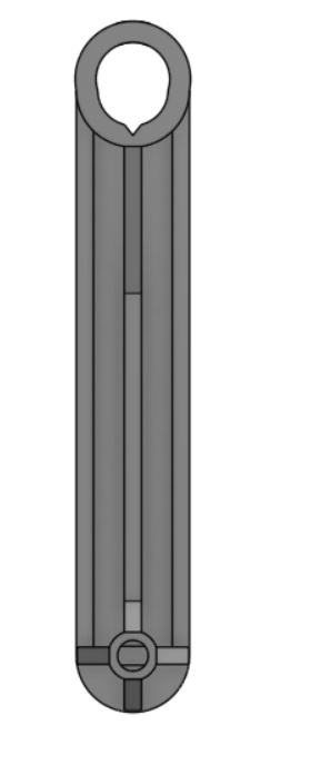
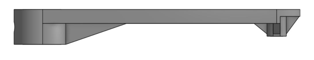
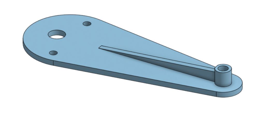
The arms have ribs to strengthen them and make them more ridgid. Below is the outer arm, the one that holds the pen.
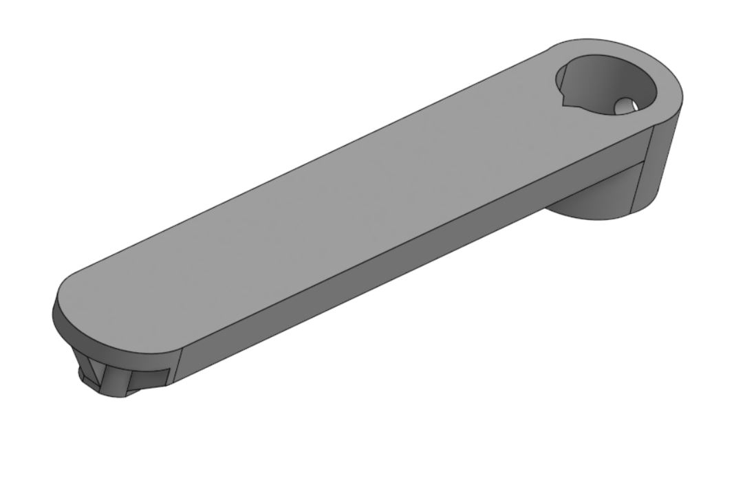
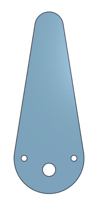
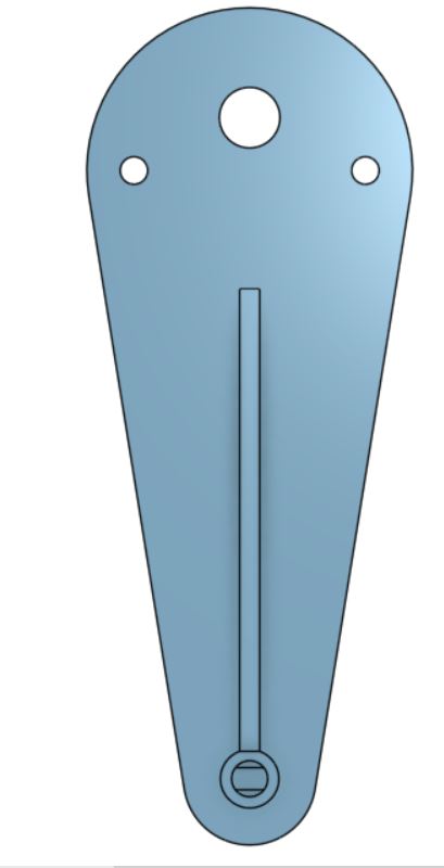
Below is the CAD model for the inner arm.
The first prototype assembled and tested. The arms were ridgid enough but the push fit connection to the shaft of the stepper motor was not ridgid enough. The stepper motor is glued onto a scrap of aluminium extrusion and clamped to the table for testing.
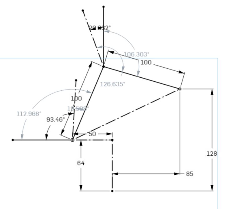
First prototype-inverse kinematics
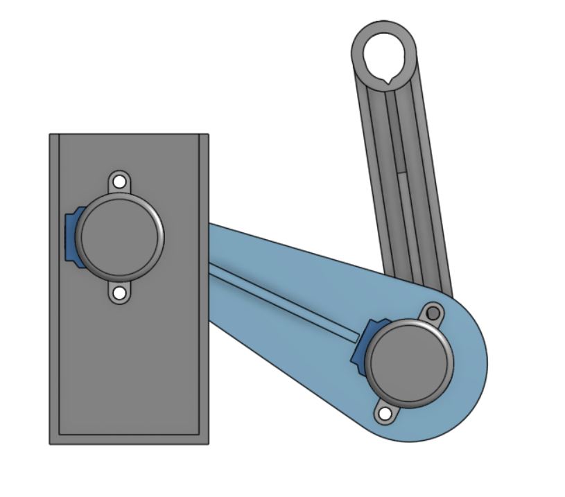
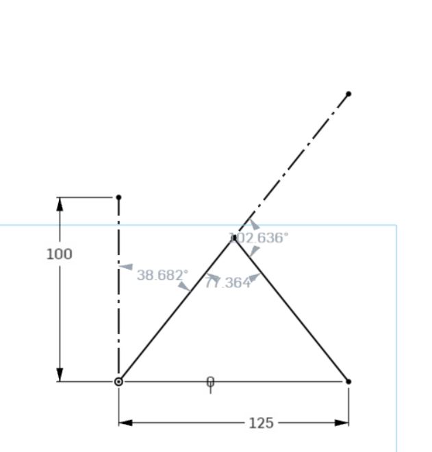
Inverse kinematics is used to convert a cartesian coordiante, an X, Y coordinate to an angle that the arms need to move to.
In the image below, the arm is at position (125, 0) the angles of the arms are 38.682 deg and 102.636 deg.
First prototype-Programming
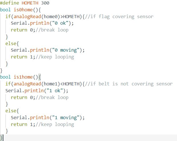
Below is the homing switch function analog channels A6 and A7 are used to read the switch. Since the pins on the microcontroller are only connected to the analog MUX, Only analogRead can be used to read the pin states.
The outer arm is first moved out of the way.
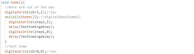
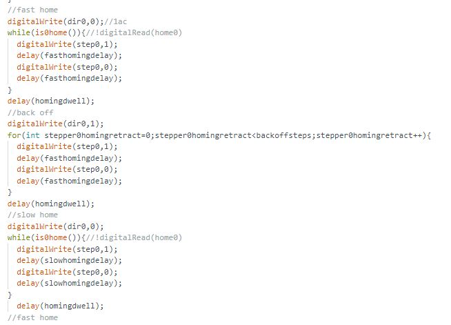
Homing is then done. First with a higher speed, then homing again with a lower speed for more accuracy.
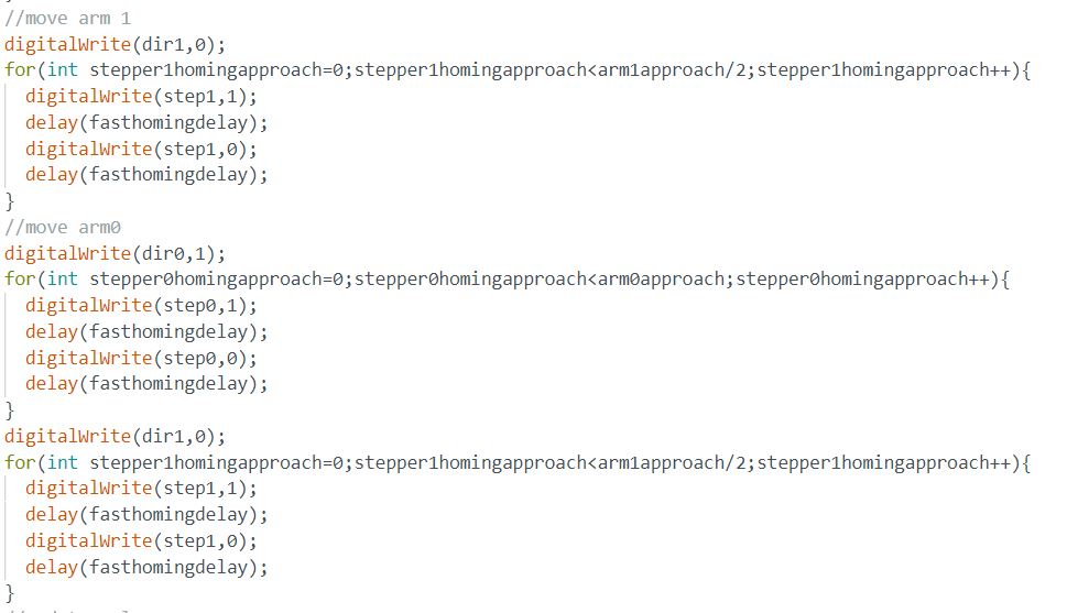
The arm is then moved to (0, 0), the lower left corner.
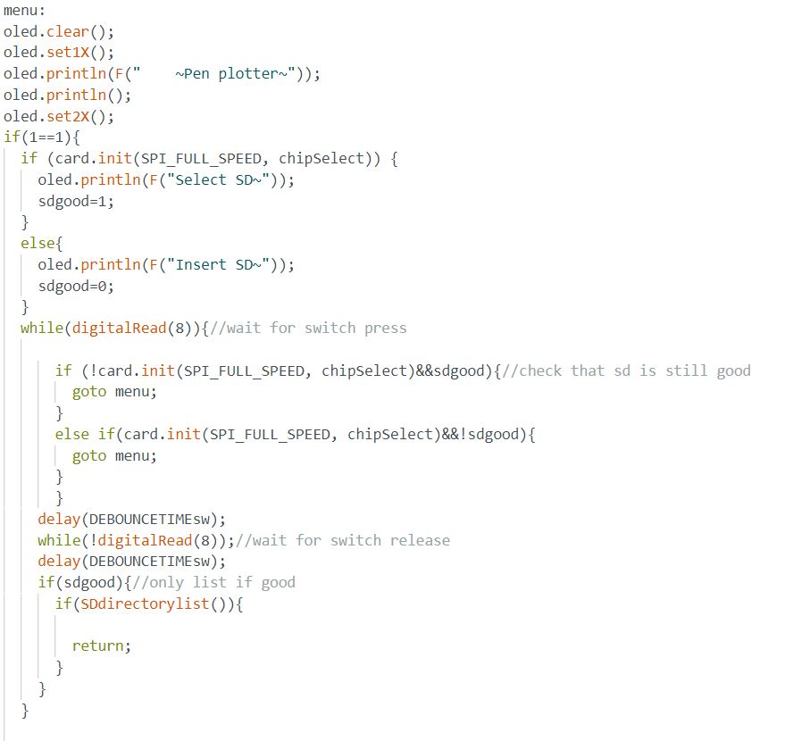
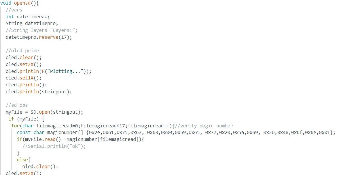
The function below polls the SD card to make sure that it is inserted.
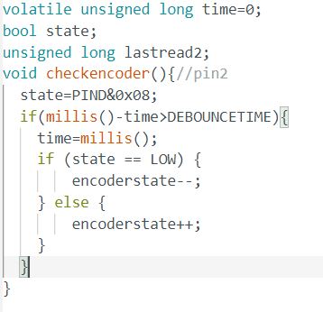
Below is the interupt service routine used to read the rotory encoder.
The magic number of the file is verified.
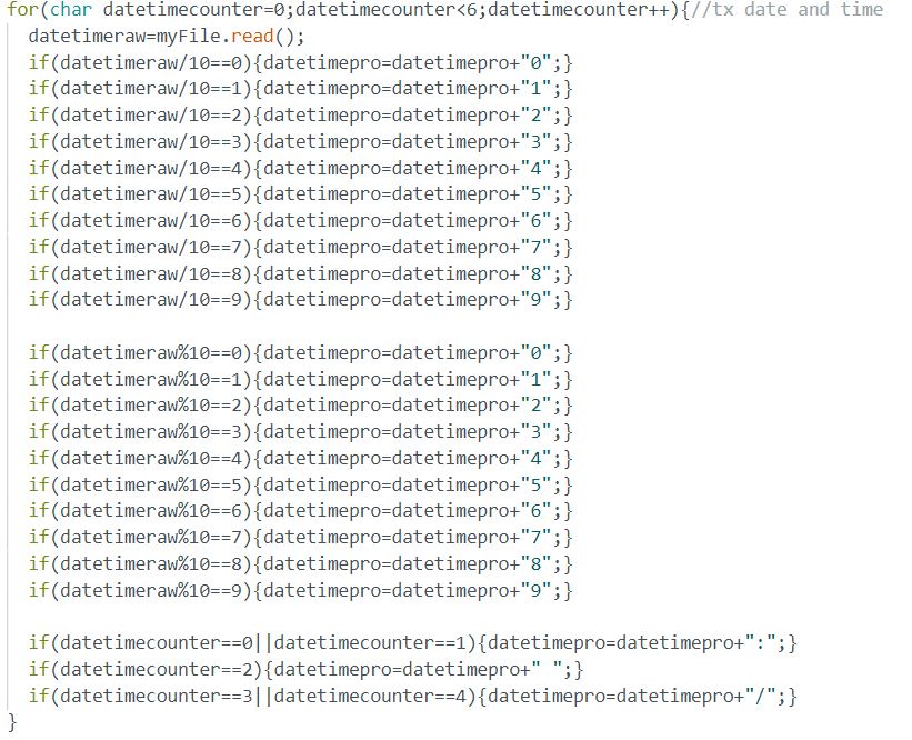
The metadata of the file is read.
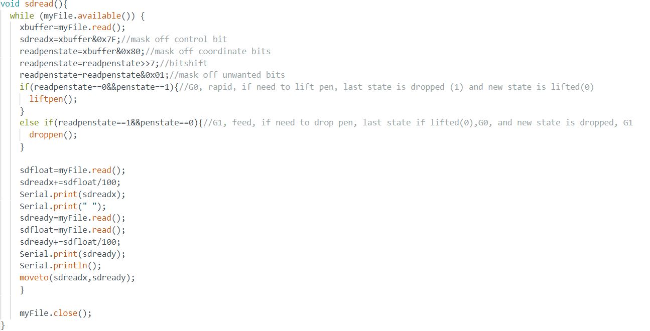
The coordinates of the toolpath is read here.
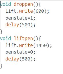
Below are the functions for lifting and dropping the pen.
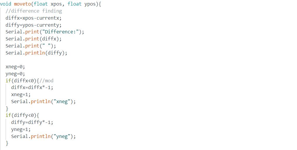
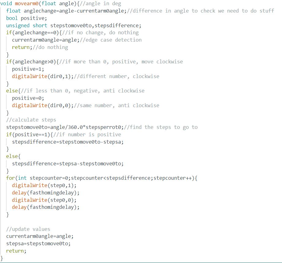
The function below calculates the linear moves for the pen plotter.
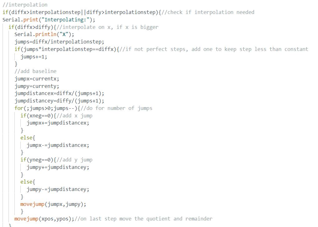
The linear moves are interpolated here so that the movement would be more accurate.
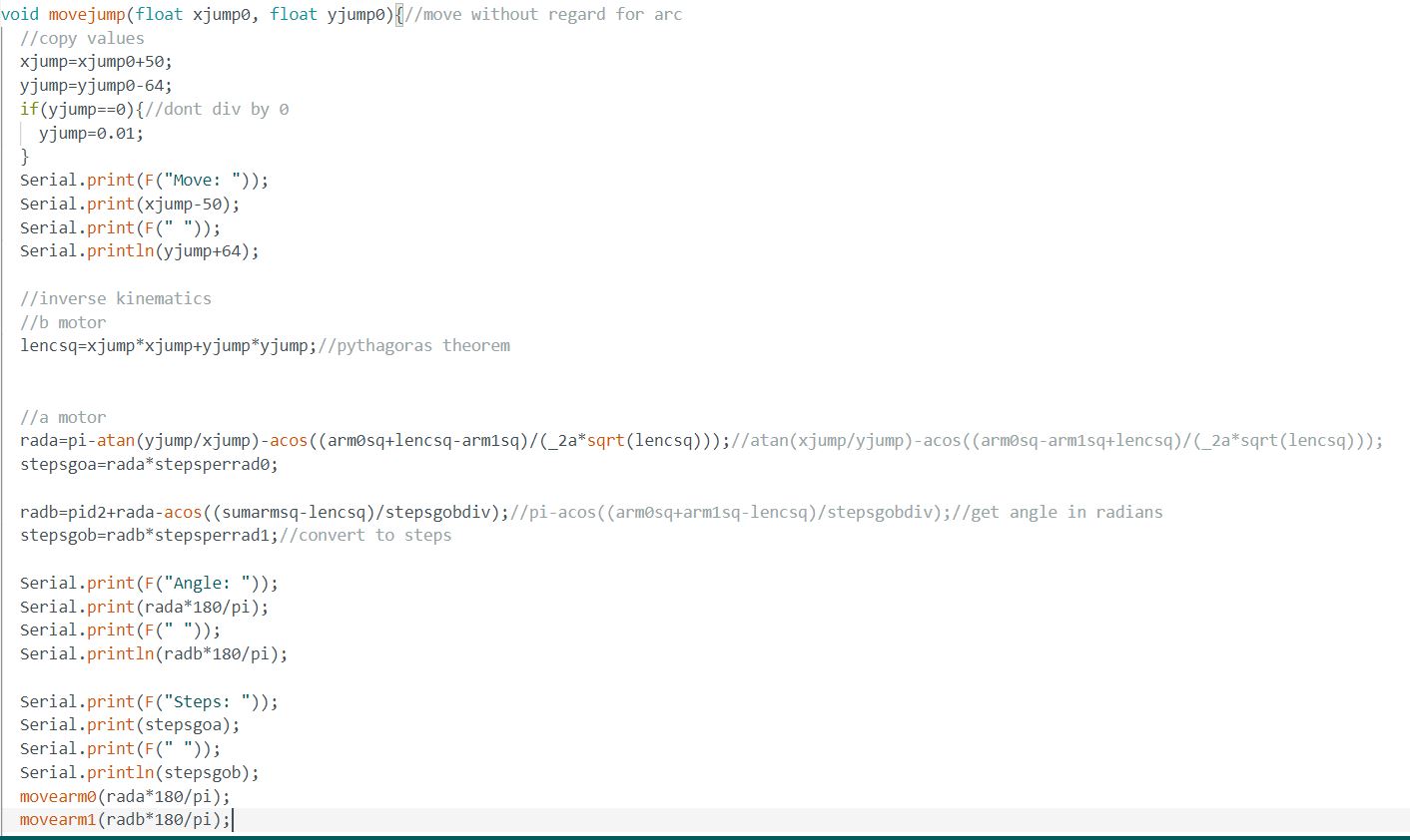
The inverse kinematics is calculated here.
Below is the function that does the timing and calculations to move the arm when plotting.
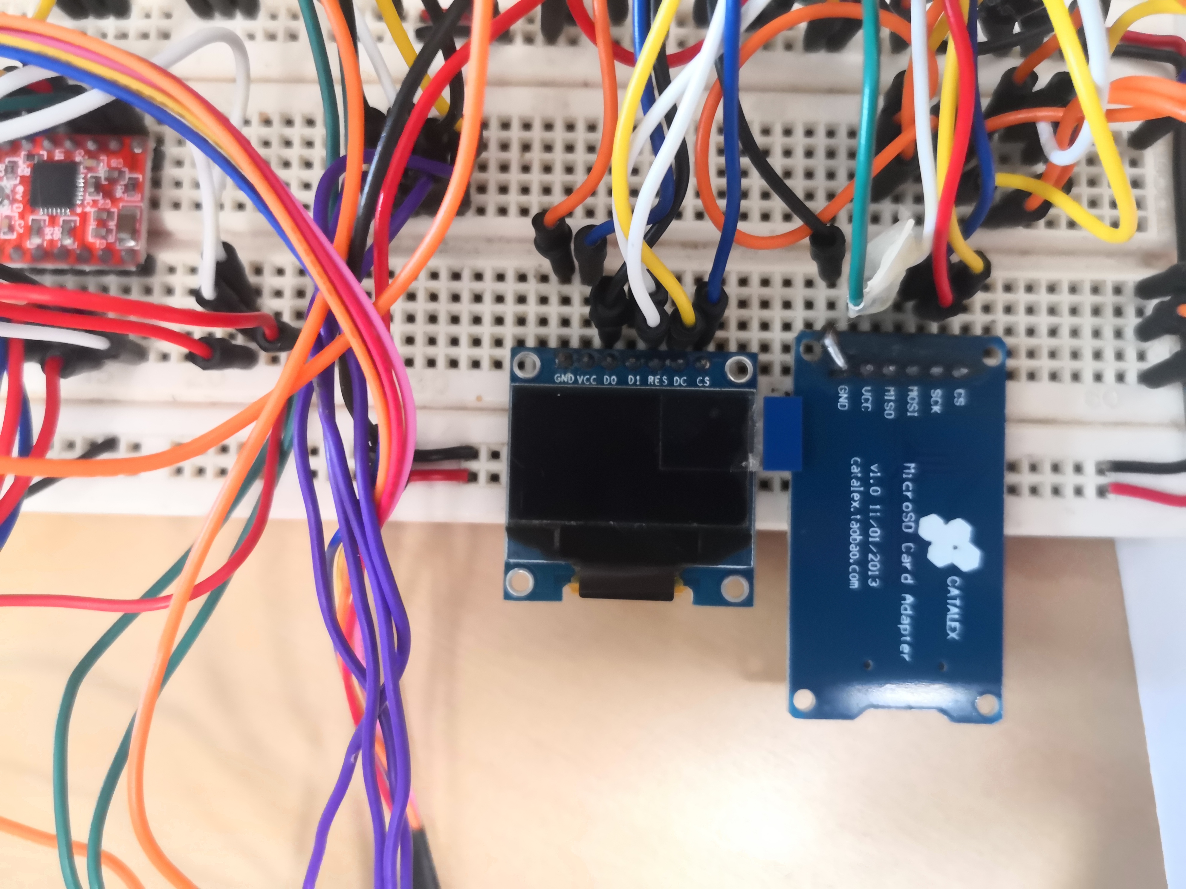
First prototype-Electronics
The electronics for the first prototype is similar to the electronics of the final prototype. The main differences is that the microcontroller used here is the arduino UNO, while the microcontroller used in the final prototype is the arduino Nano. There is also an additional servo motor.
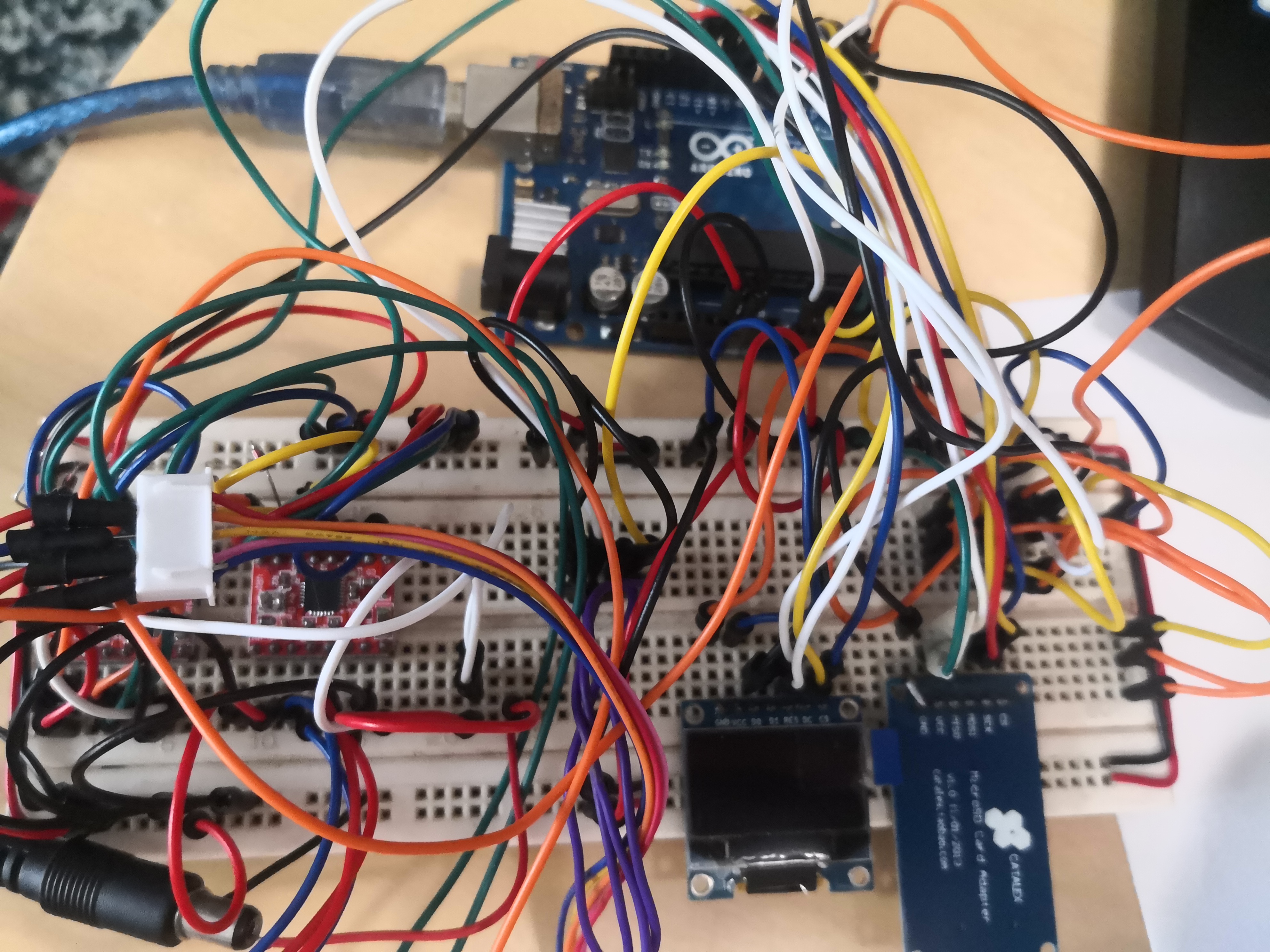
The same SD card and OLED screen is used. The menu selection is done with jumper wires as switches.
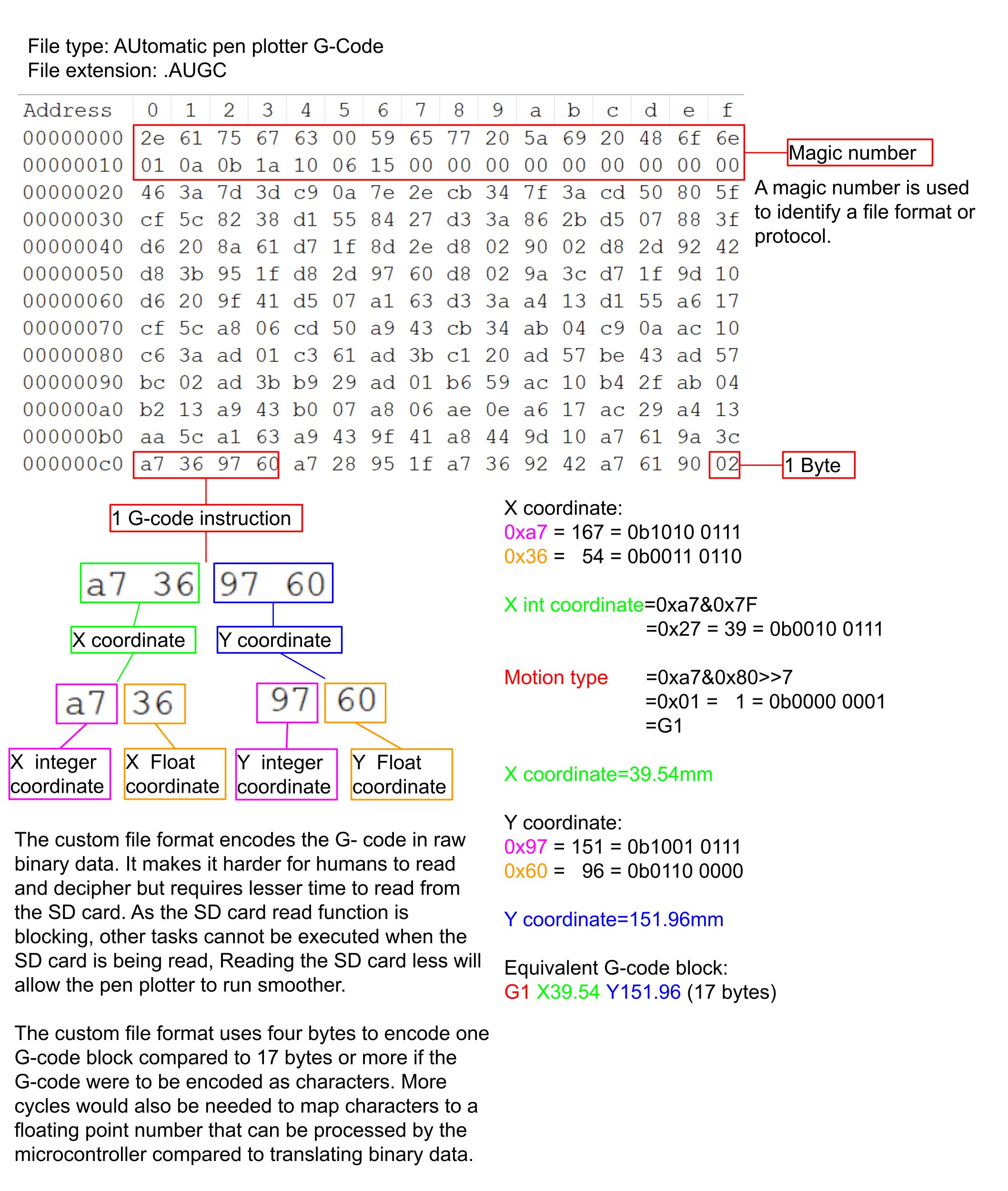
First prototype-file format
First prototype-toolpath generation
The toolpath is generted by using Cura. The resulatnt toolpath will only consist of rapid moves and linear moves.
First, the STL file to be plotted is opened in Cura.
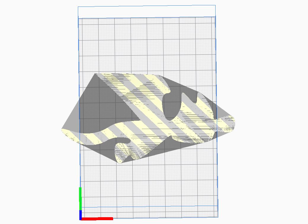
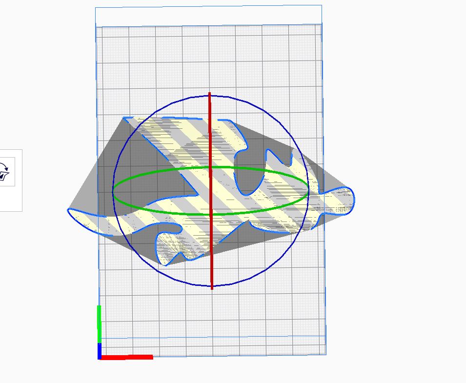
The Mesh is rotated to the correct orientation to fit into the area that the pen plotter can plot.
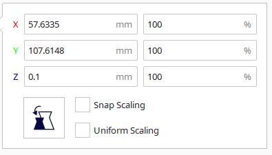
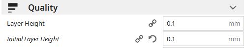
The thickness of the mesh will need to be 0.1mm.
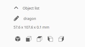
If the thickness is not 0.1mm, the scale would need to be changed to 0.1mm.
The layer height also needs to be 0.1mm.
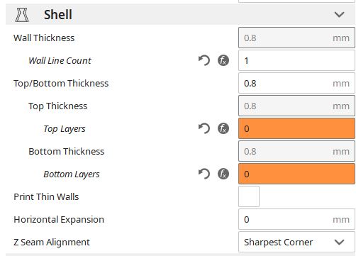
There must be 0% infill, 0 top and bottom layers and only 1 outer wall.
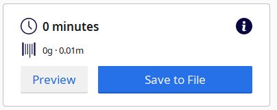
Once the settings are done, click on slice.

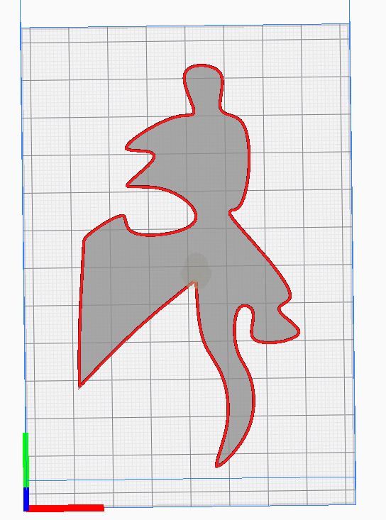
Select preview to check the toolpath.
Previewed toolpath

Toolpath generation
G-code compression
To reduce the time taken by the microcontroller to read the G-code file. the G- code is compressed and converted to another file format.
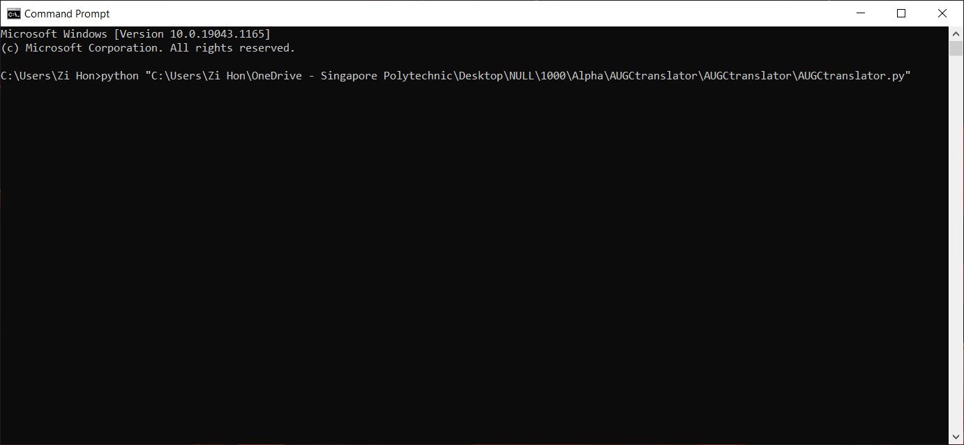
To begin open command prompt. Python must be installed beforehand.
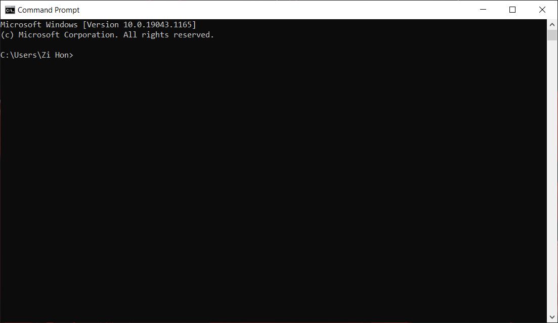
Type "python", followed by the python file location.
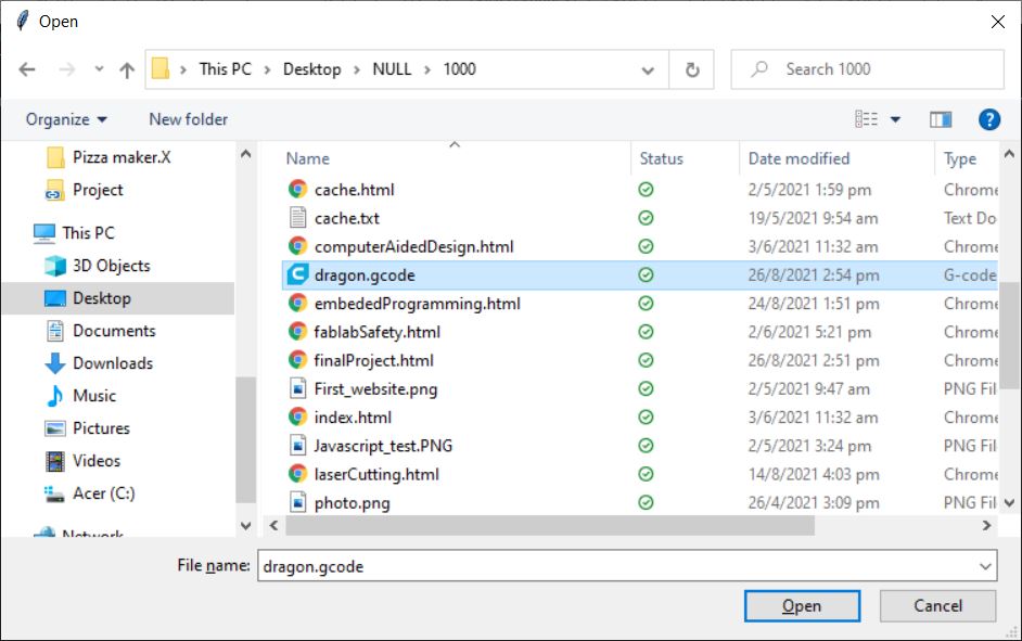
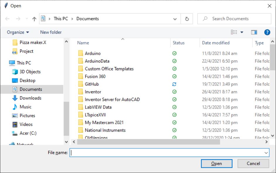
A dialog will appear to choose a file.

Choose a file and click open.
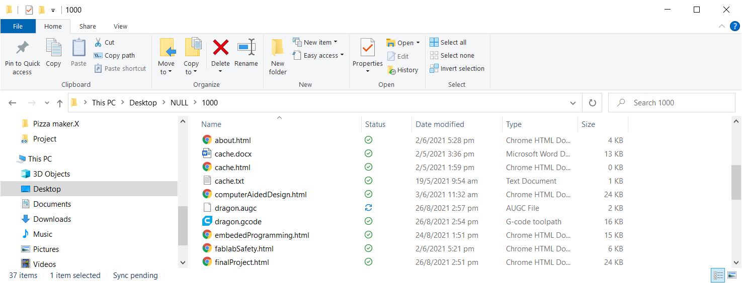
If the selected file is a G-code file, the file should be converted with no errors and the command prompt can be closed. Below shows the converted file.
Click here to download Python project.
First prototype-Testing
Below is the only test of the first prototype. After this test is was clear that the stepper motors used were very inadequate and the deign was very much not ridgid enough.
First prototype homing cycle
Inserting Sd card and plotting. Wires are used in place of the rotory encoder.
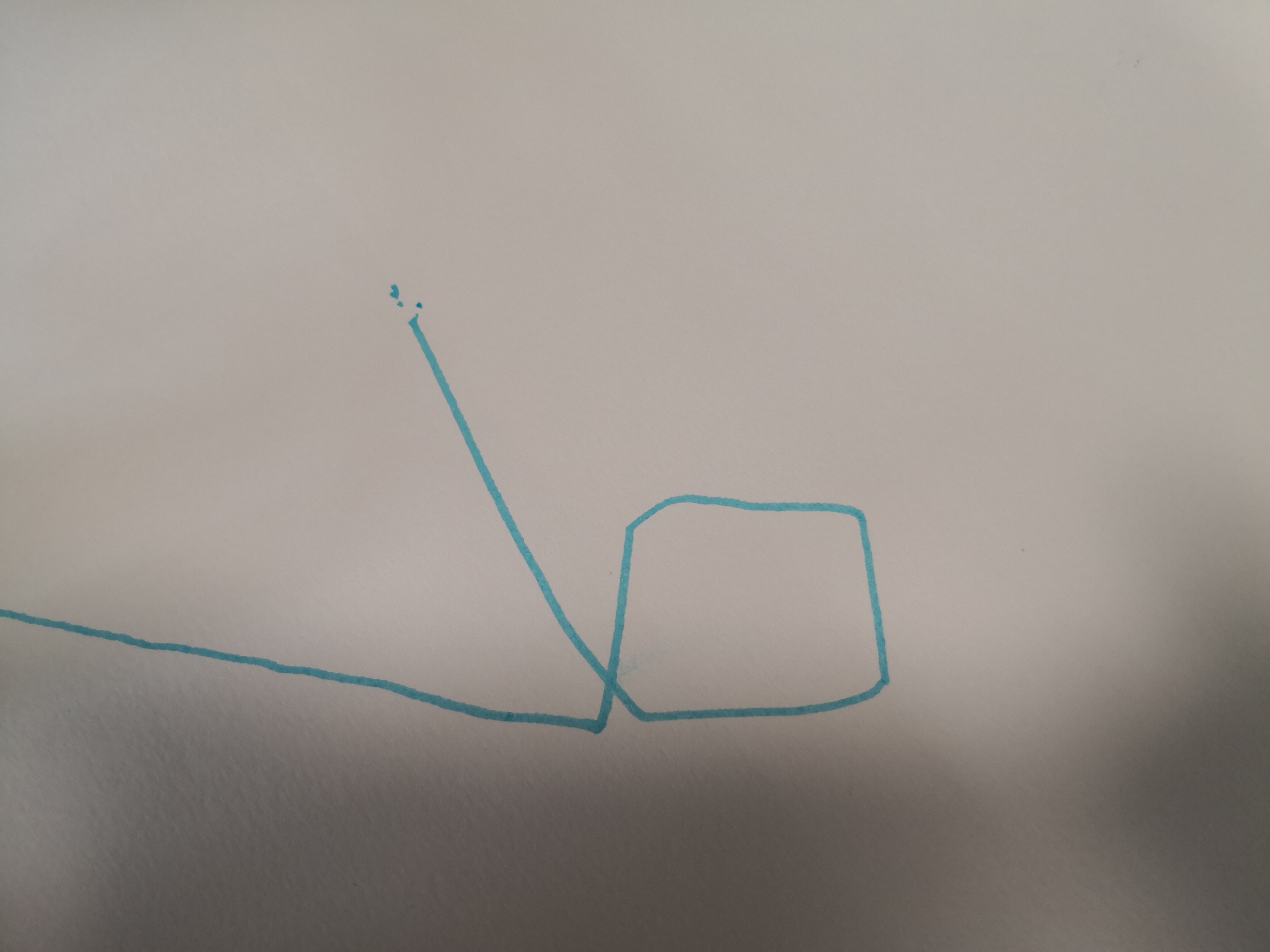
The result is a square.... Sort of...
First prototype-problems
Stepper motors
The first prototype was not meant to be the final prototype. However the first prototype showed that the motors chosen were not suitable.
The stepper motors were too weak and was not reliable. It would constantly skip steps and even when converted to bipolar. They also had a large ammount of backlash in them shown in the video below.
This problem is solved in later prototypes by using a different more powerful stepper motor, a NEMA 17 stepper motor.
Lack of ridgity
The prototype was not meant to be as ridgid as the final prototype but the flexibility in the current design showed that the final design would need to be significantly stronger.
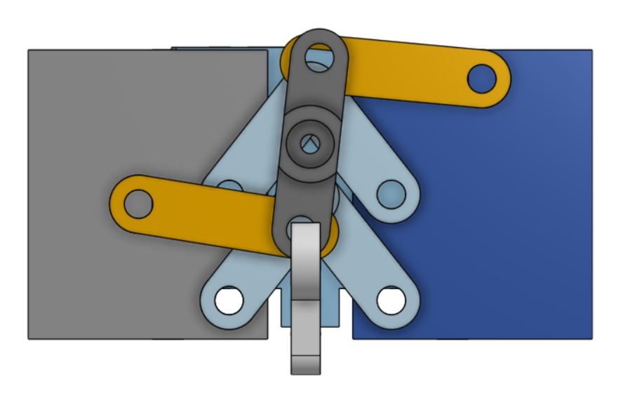
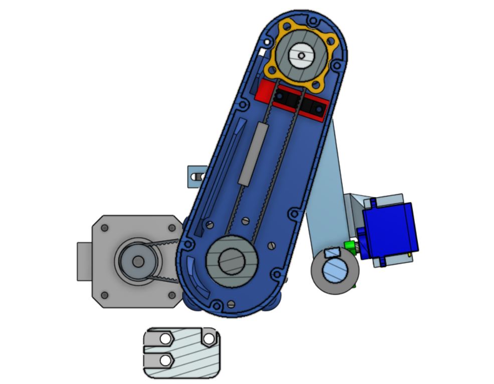
Second prototype-CAD
Cad assembly of the whole pen plotter.
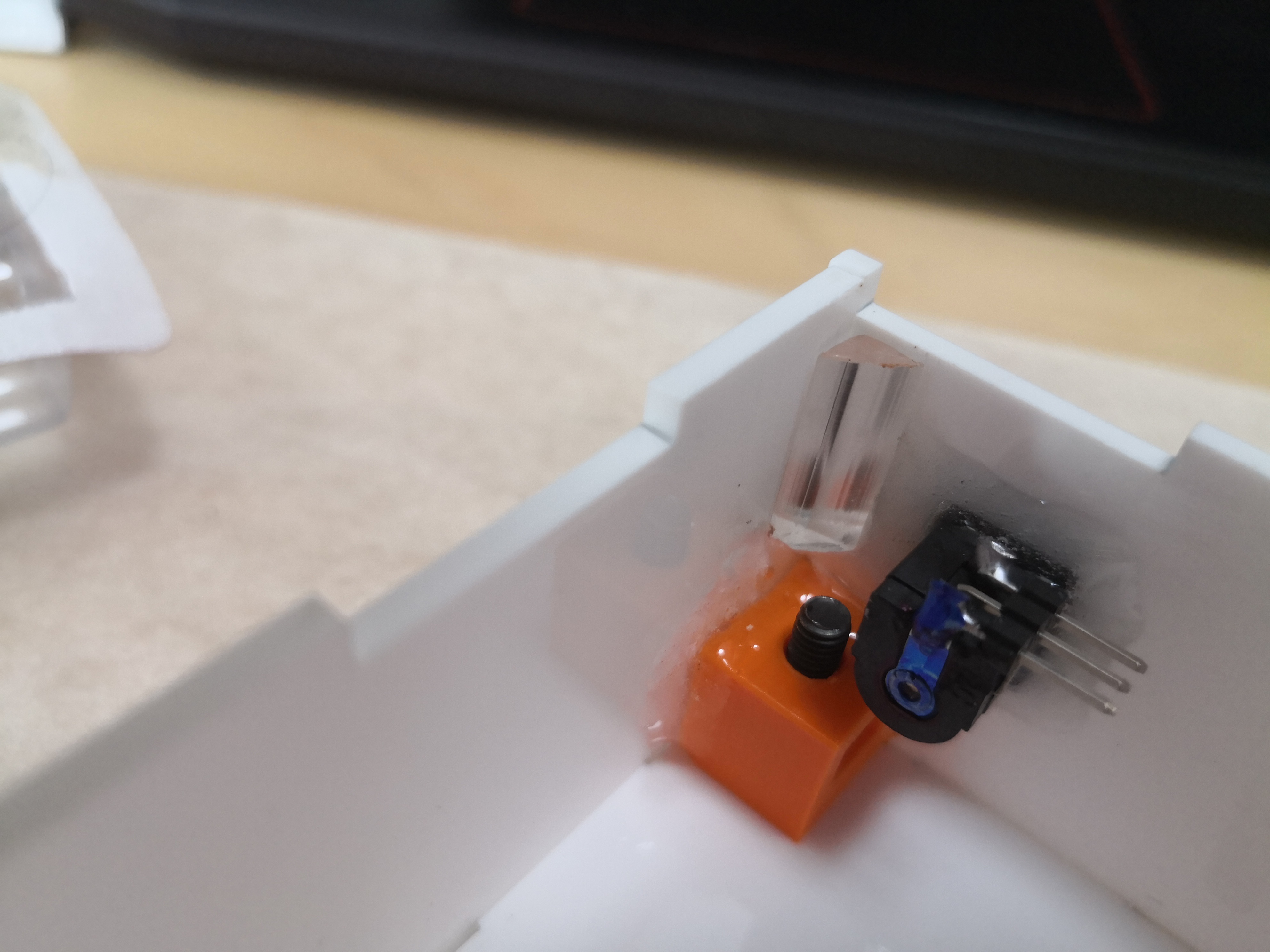
End efector assembly. It was sopposed to clamp the pen after changing its height to be more ridgid. The final design was simplified as such a complex design was not likely to work well and a simpler design would be sufficient.
Close up view of the pulley.
Inner arm pulley.
The parts were 3d printed and tested.
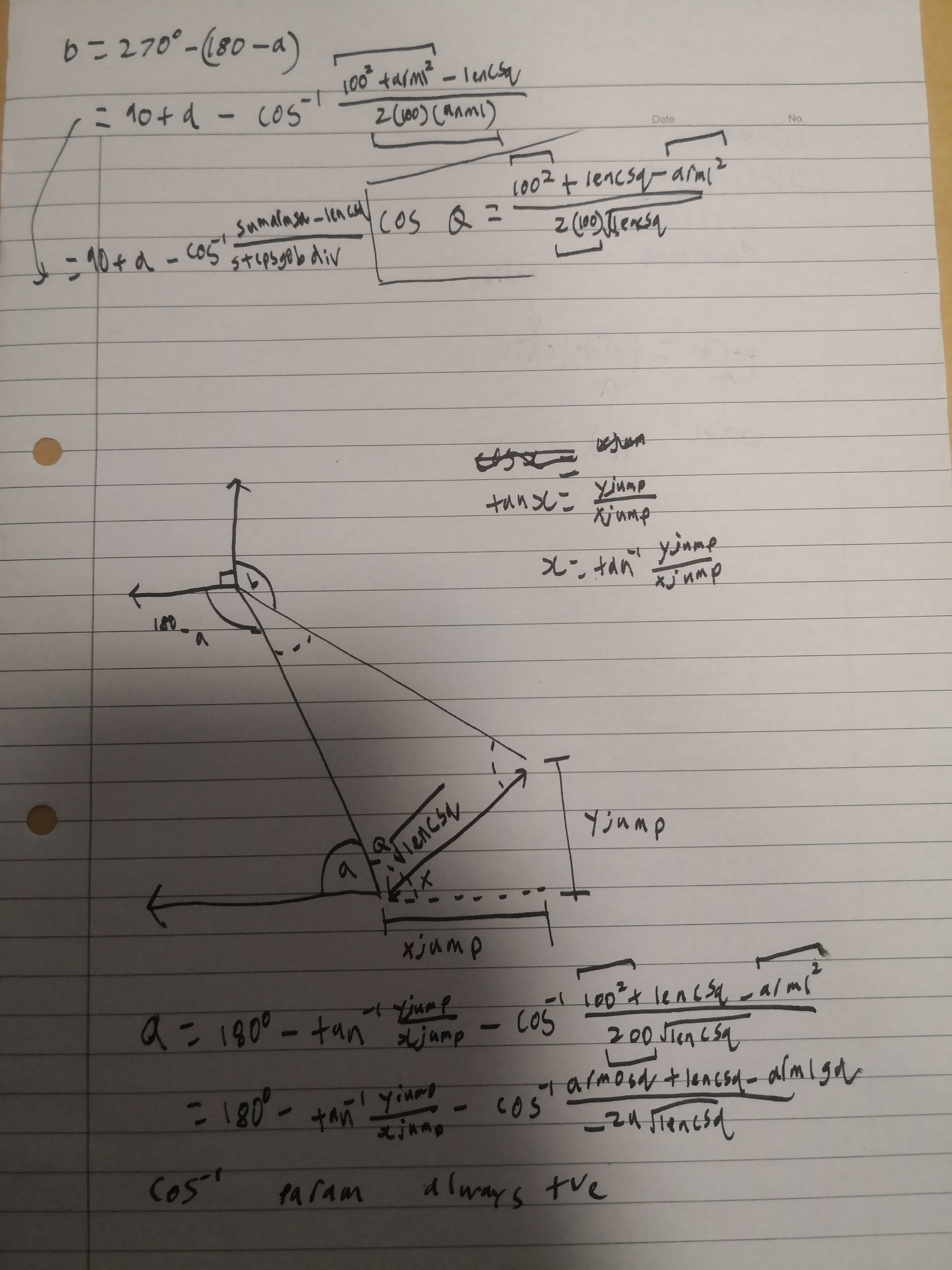
Second prototype-inverse kinematics
Inverse kinematics is used to convert a cartesian coordiante, an X, Y coordinate to an angle that the arms need to move to.
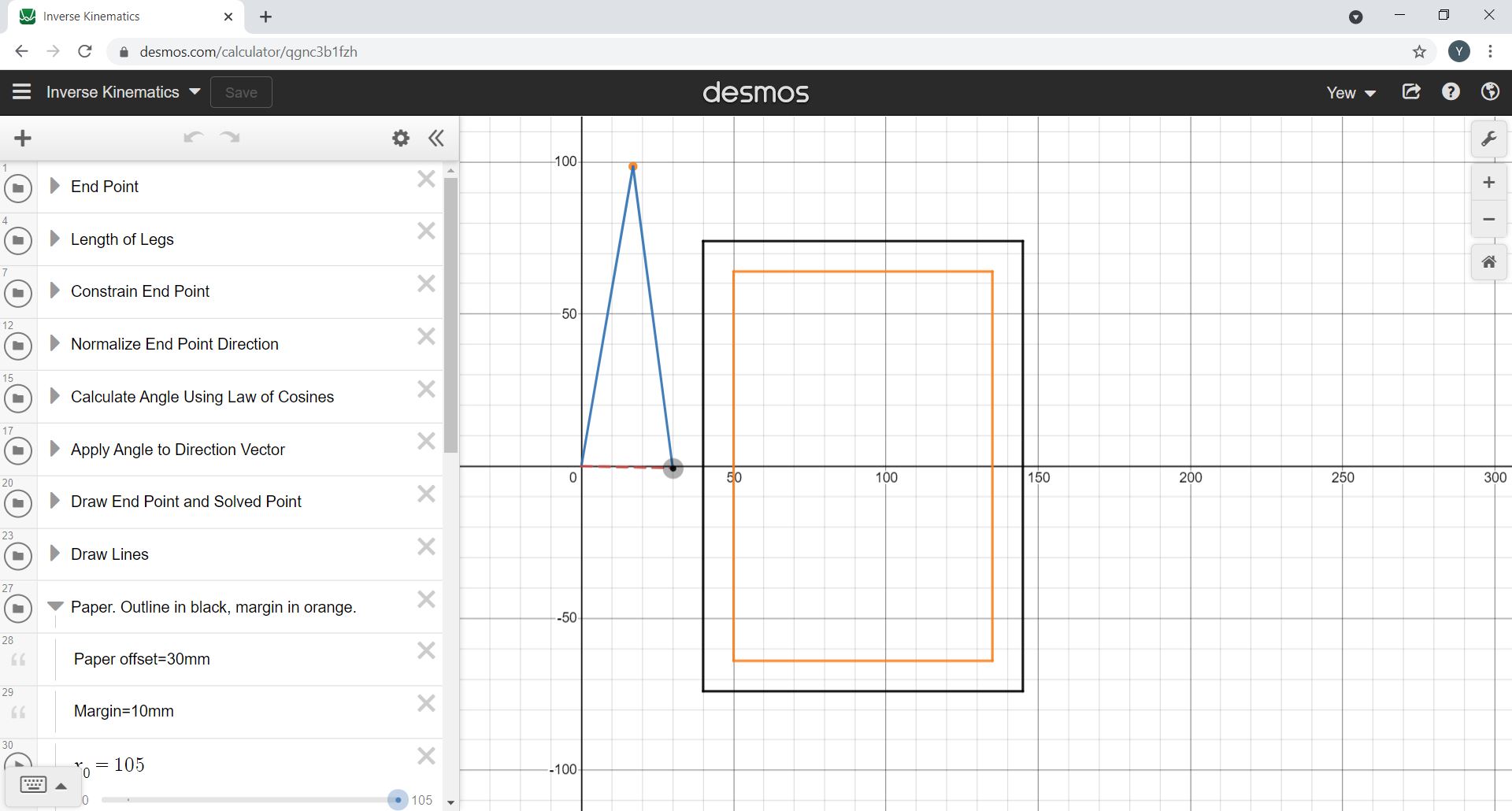
Click here to view the Desmos graph.
Second prototype-problems
Inconsistent homing
The homing of the plotter is inconsistent. In the videos below, it can be seen that the plotter homes to two different positions.
This is because the endstop is tiggered at two times for the inner arm because of the gear ratio.
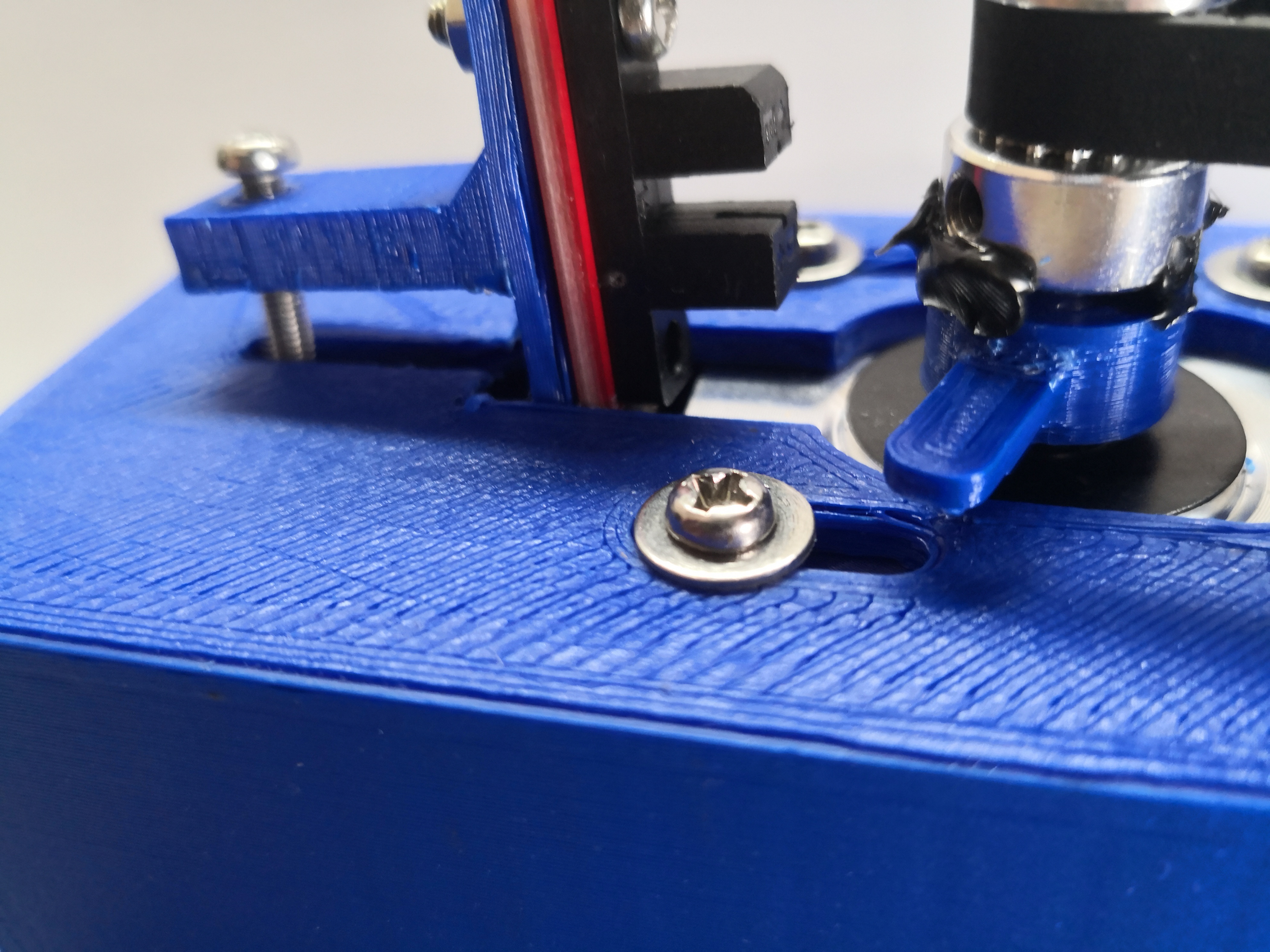
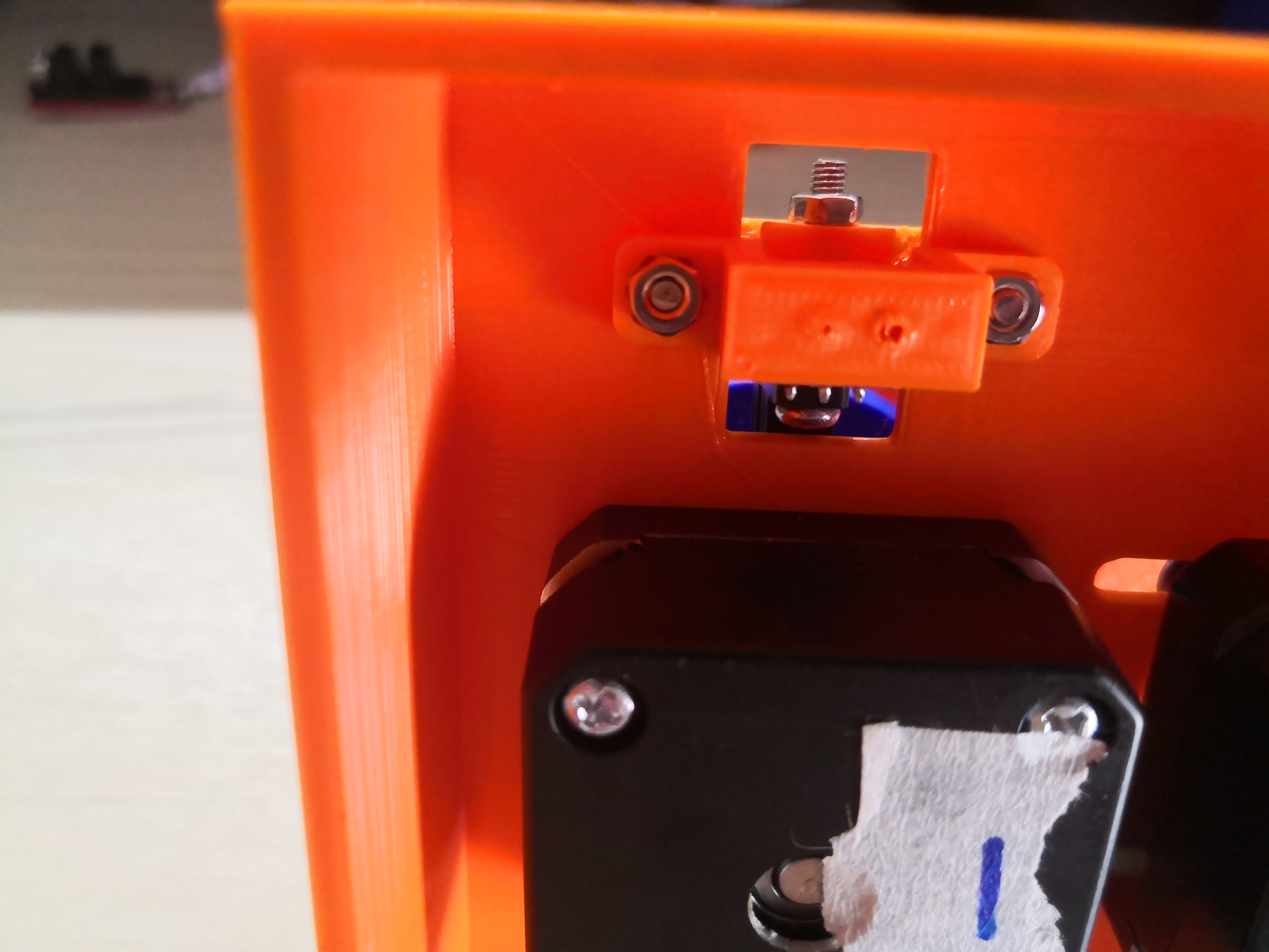
This problem is fixed in the final prototype by moving the endstop to the larger pulley.
Limited travel for outer arm.
The rotation for the outer arm is limited because the endstop is placed in the wrong position.
The endstop is moved to the end near the bearing in the final prototype.
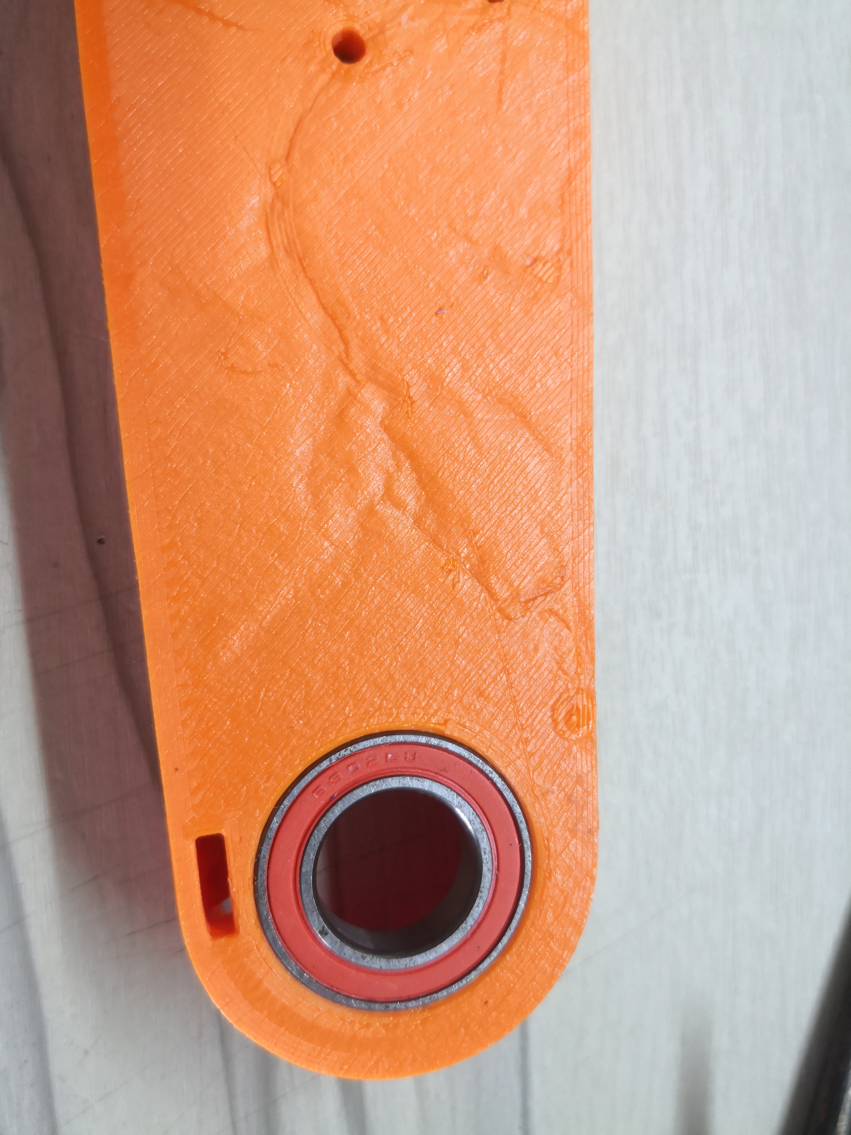
Weak cable trench
The cable trench broke off and could no longer hold the wire.
This was because the cable trench was only 0.8mm thick and was fixed by thickening the wall and chamfering it to make it stronger.
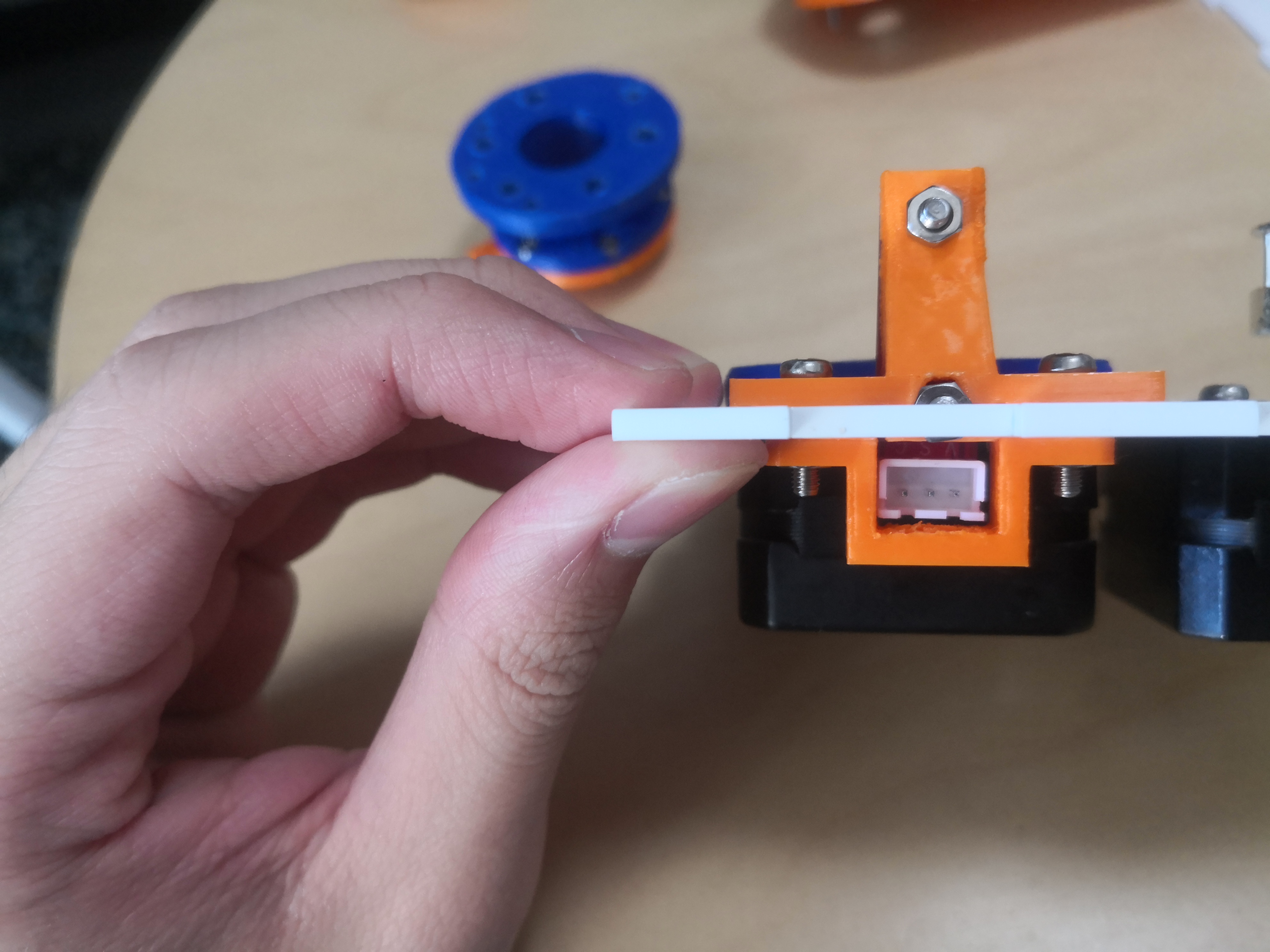
Loose rotational joints
At the joints, there is some play that amkes the plotter inaccurate.
This is because the bearing has a loose fit and has been fixed in the final prototype with larger bearings.
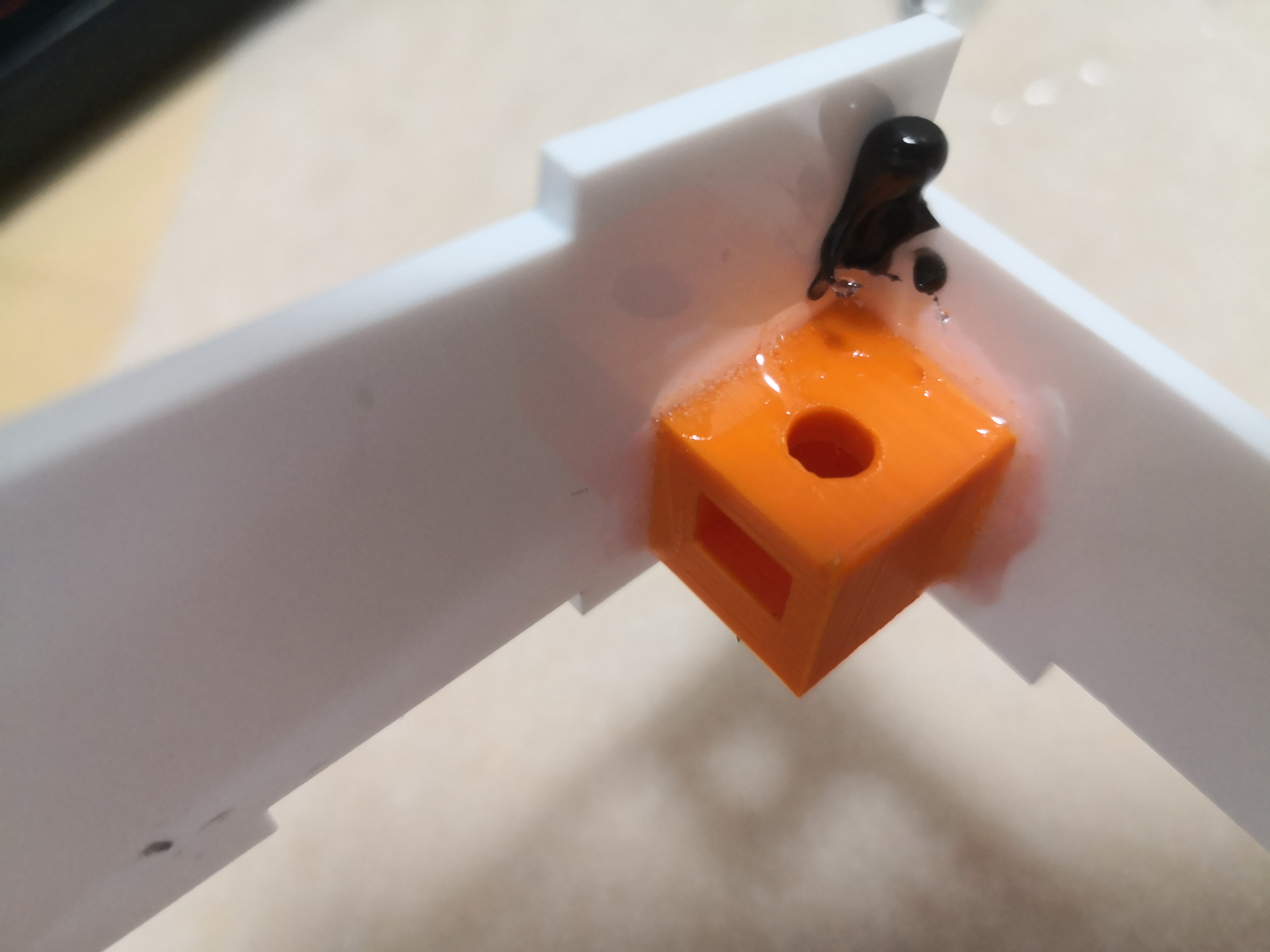
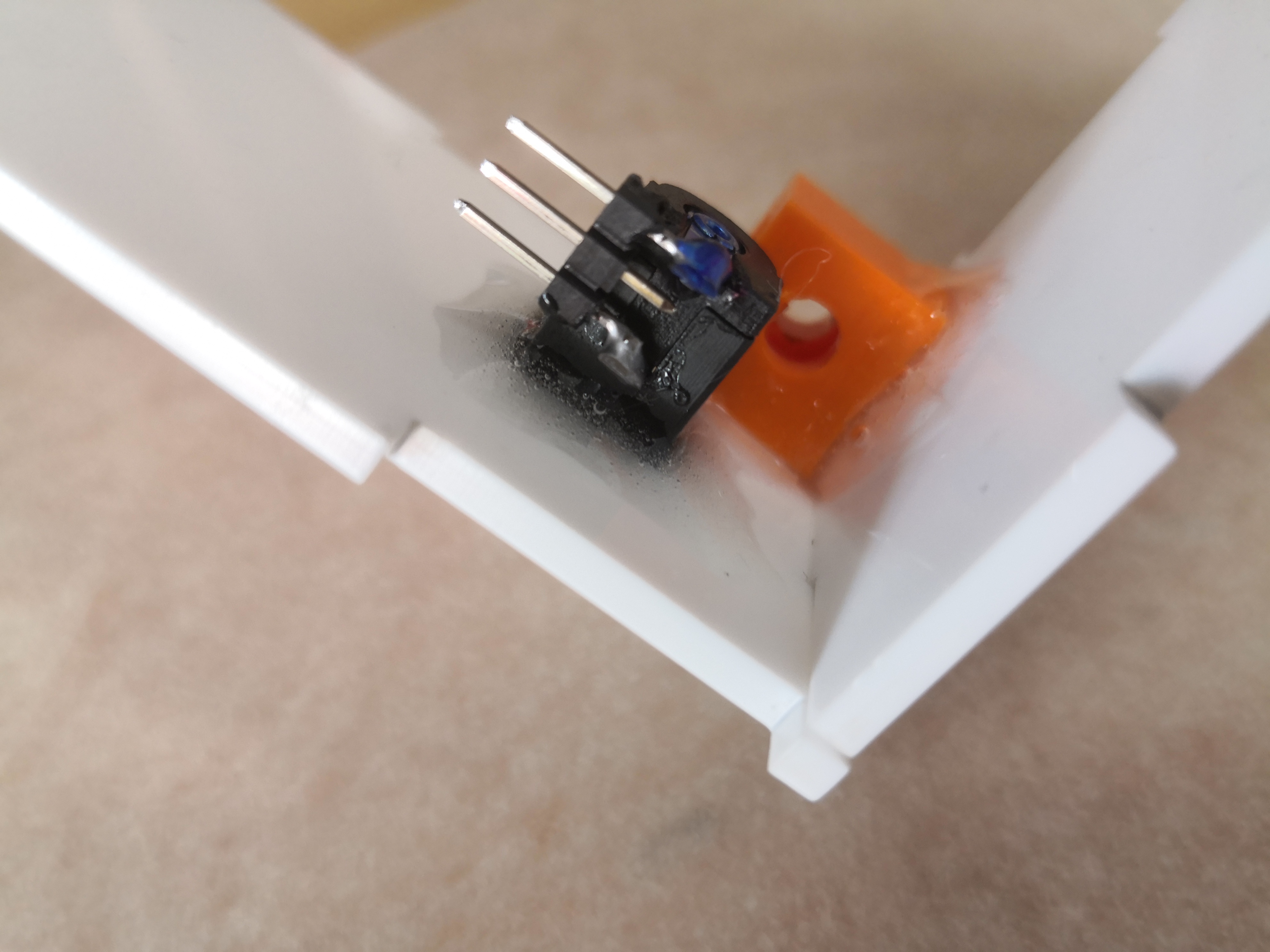
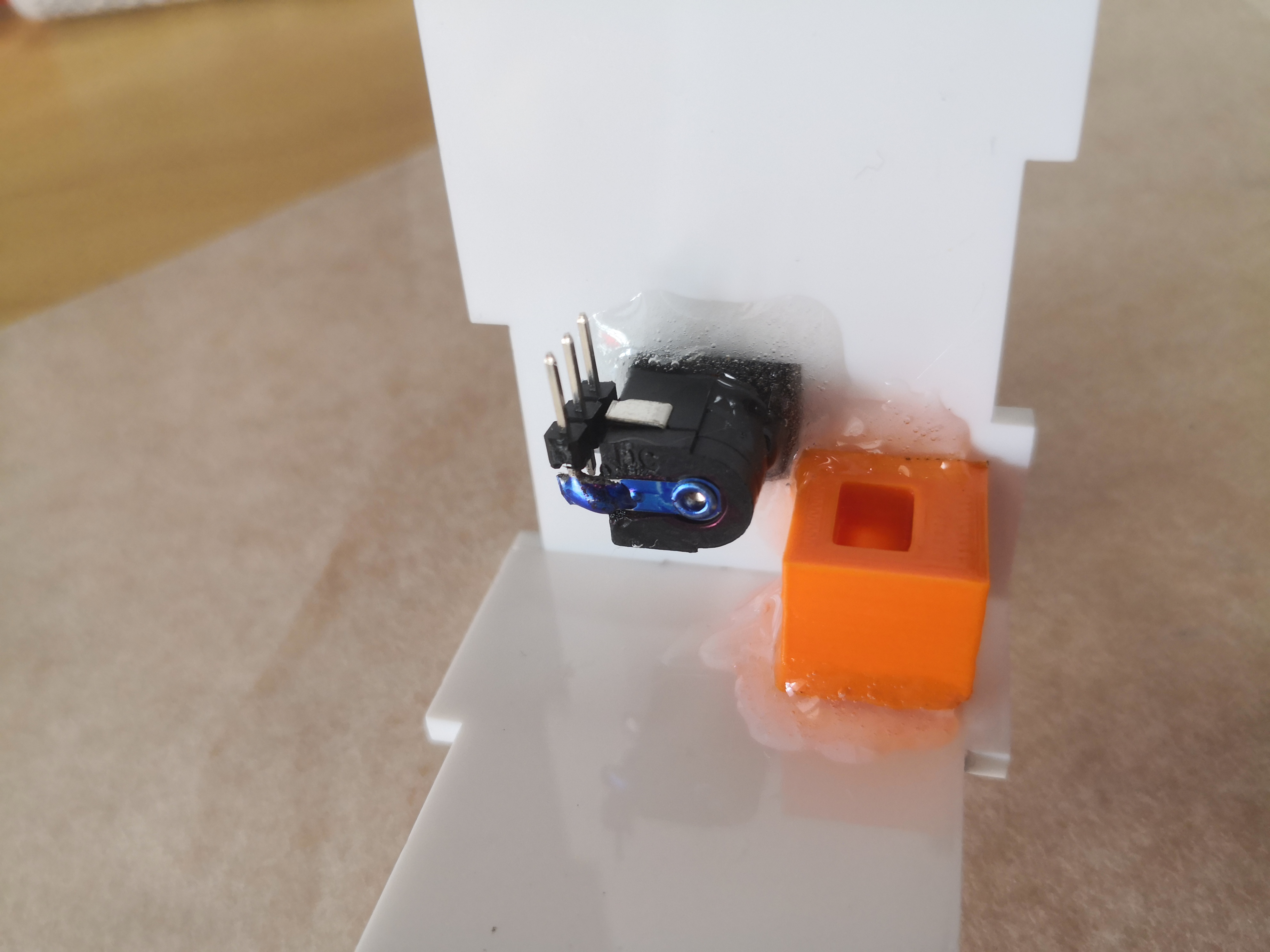
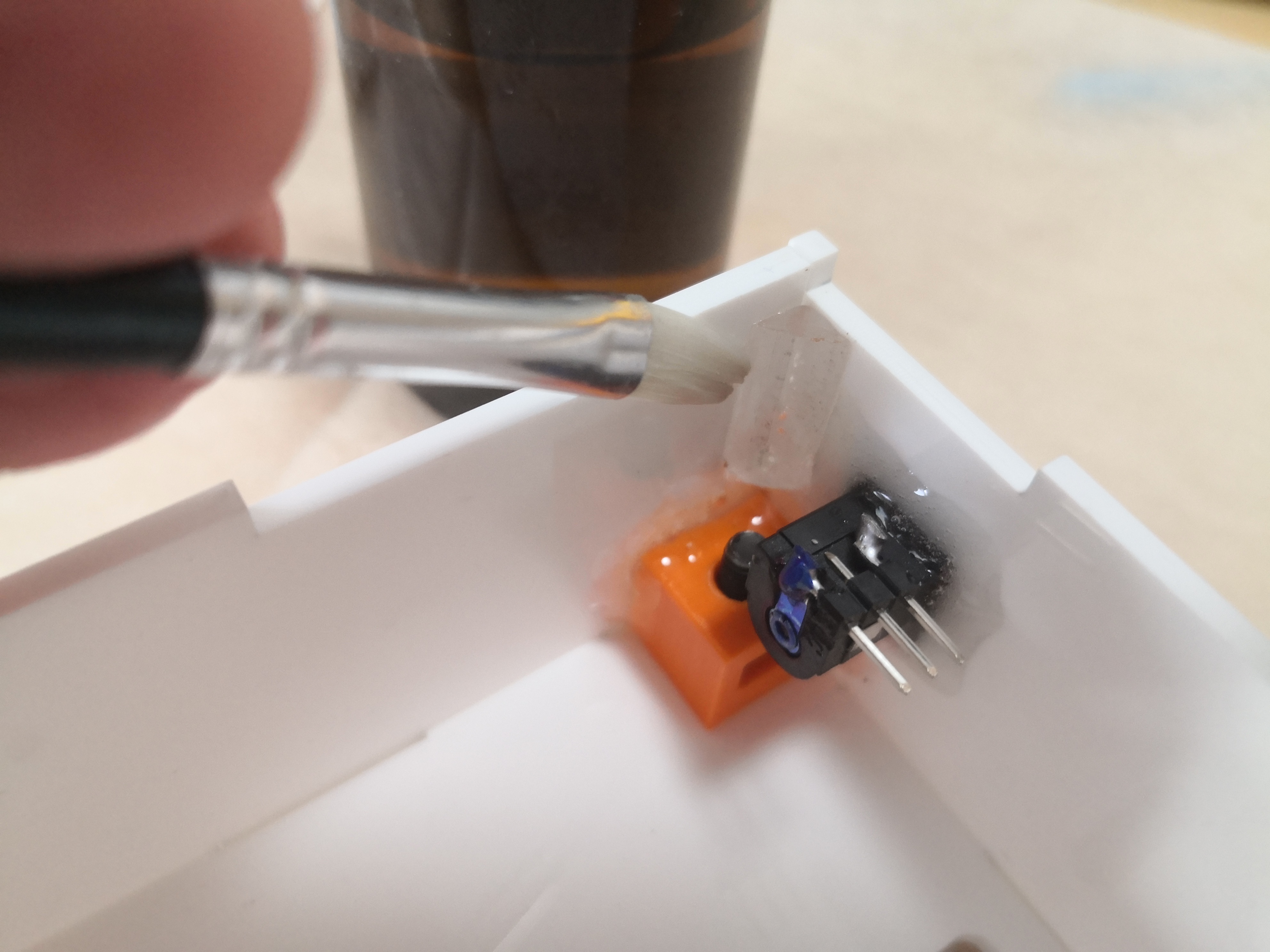
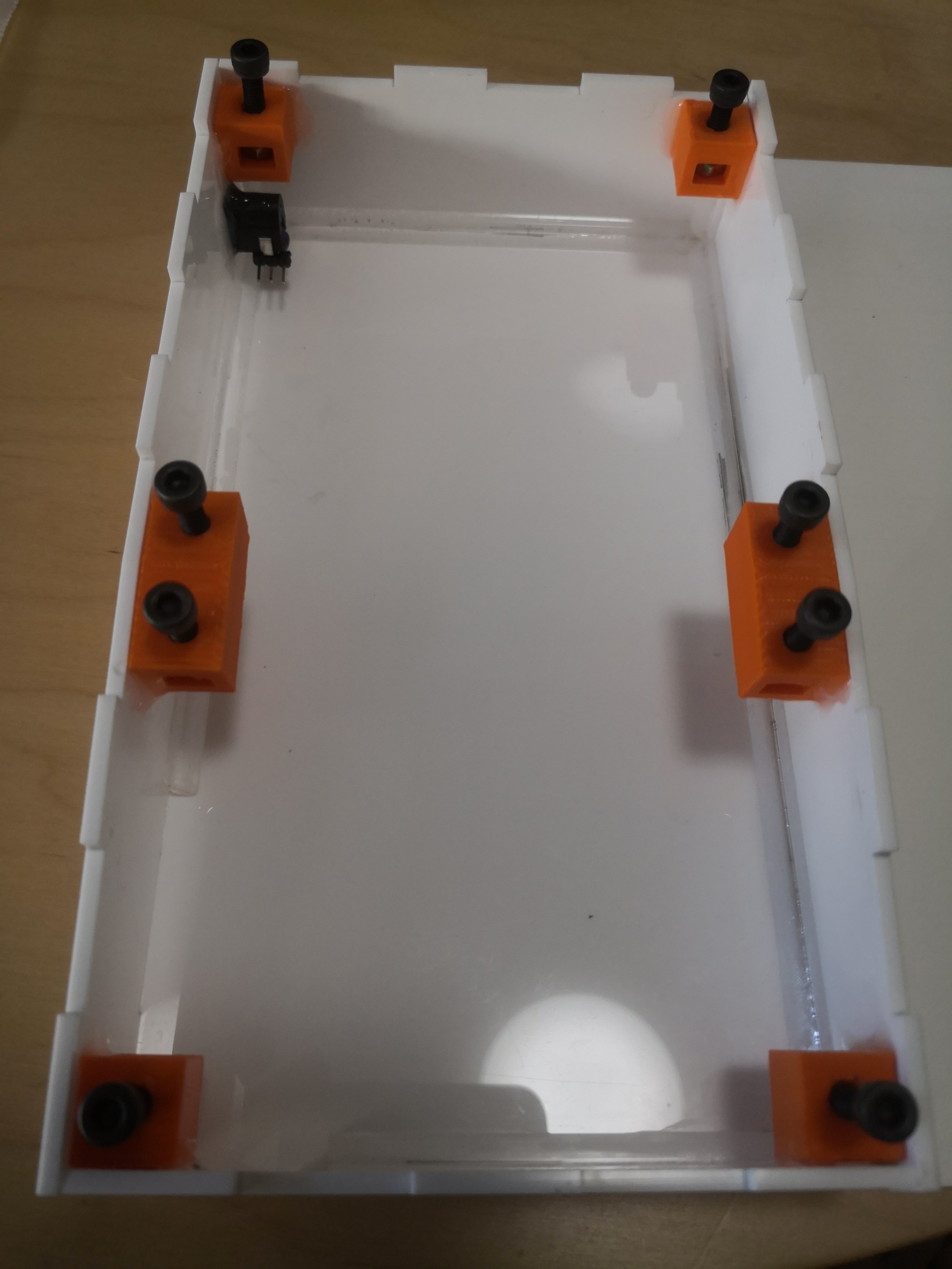
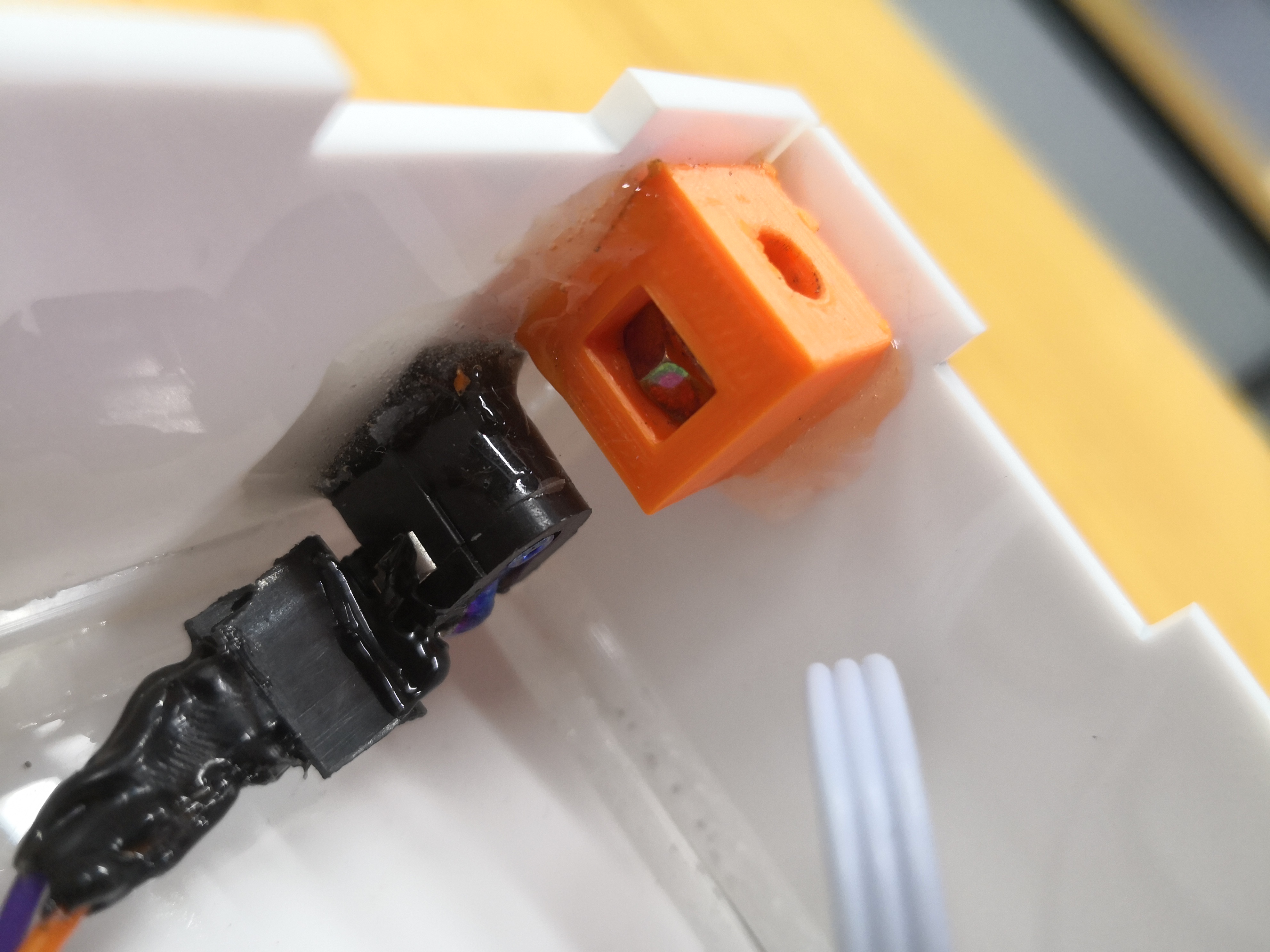
The switch was moved and fixed with hot glue and the result was better.
Backlash
The pulley was loose, casuaing the motion to be inaccurate.
This was fixed by using a ball bearing to constrain the motion of the pulley.
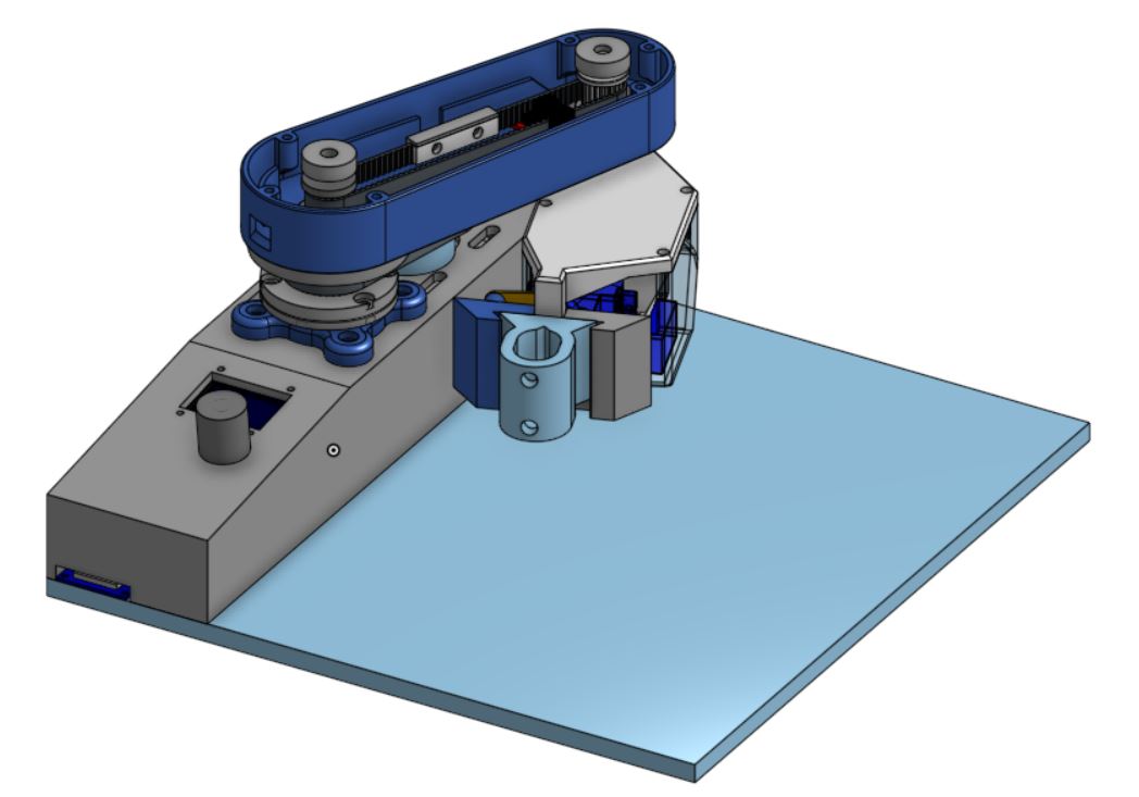
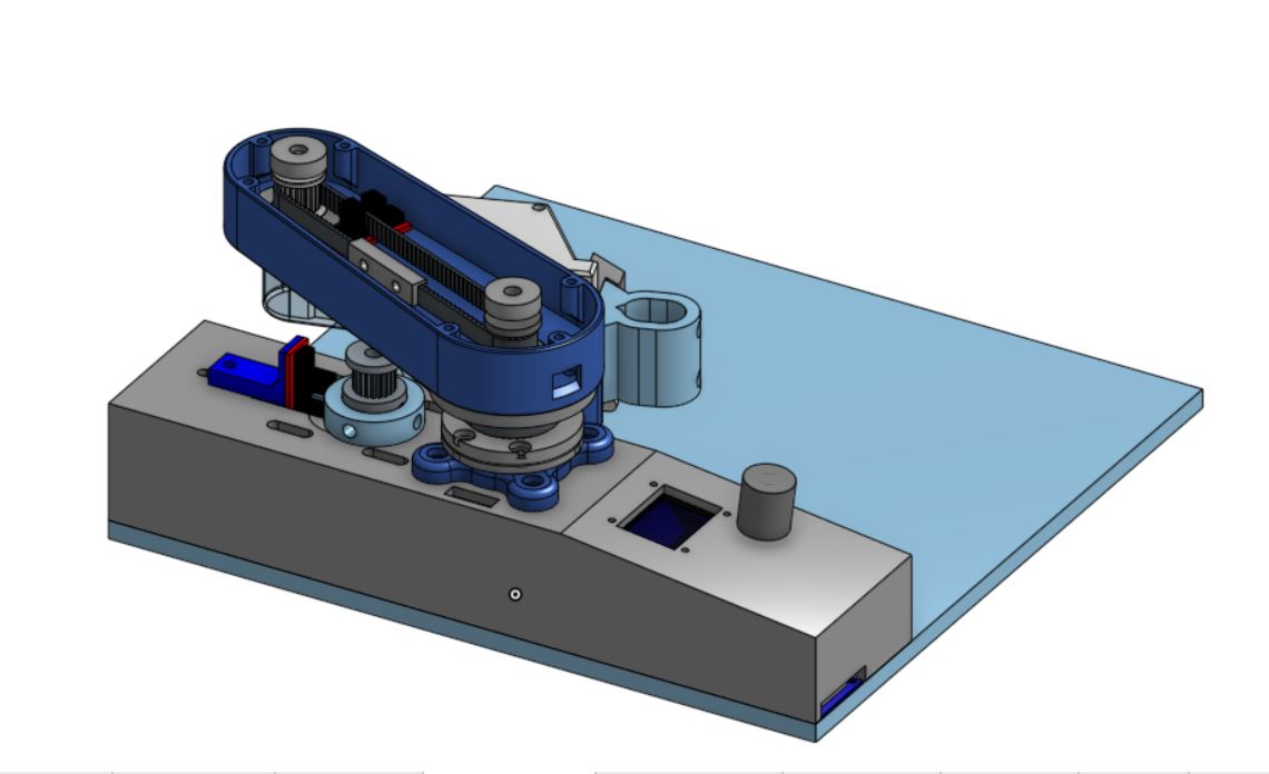
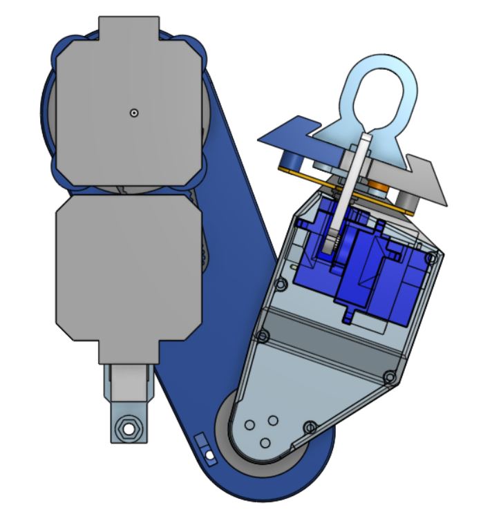
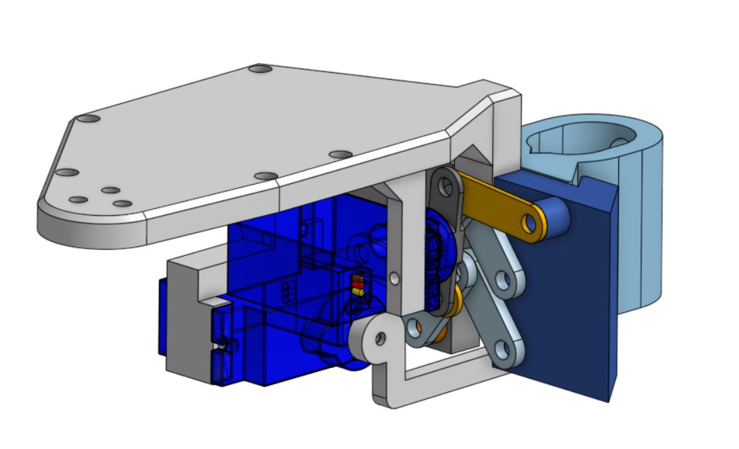
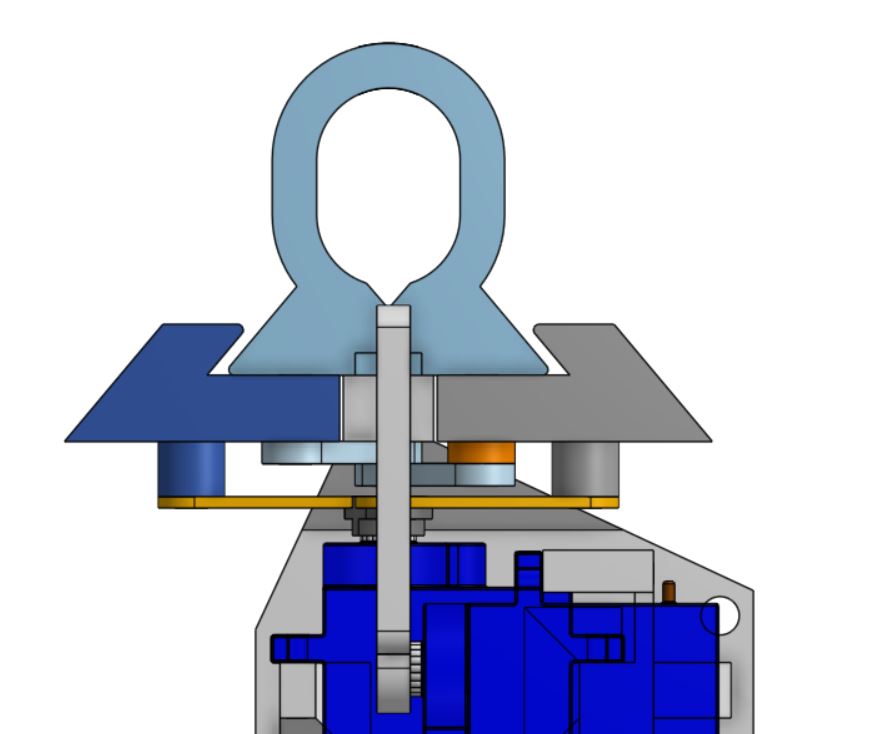
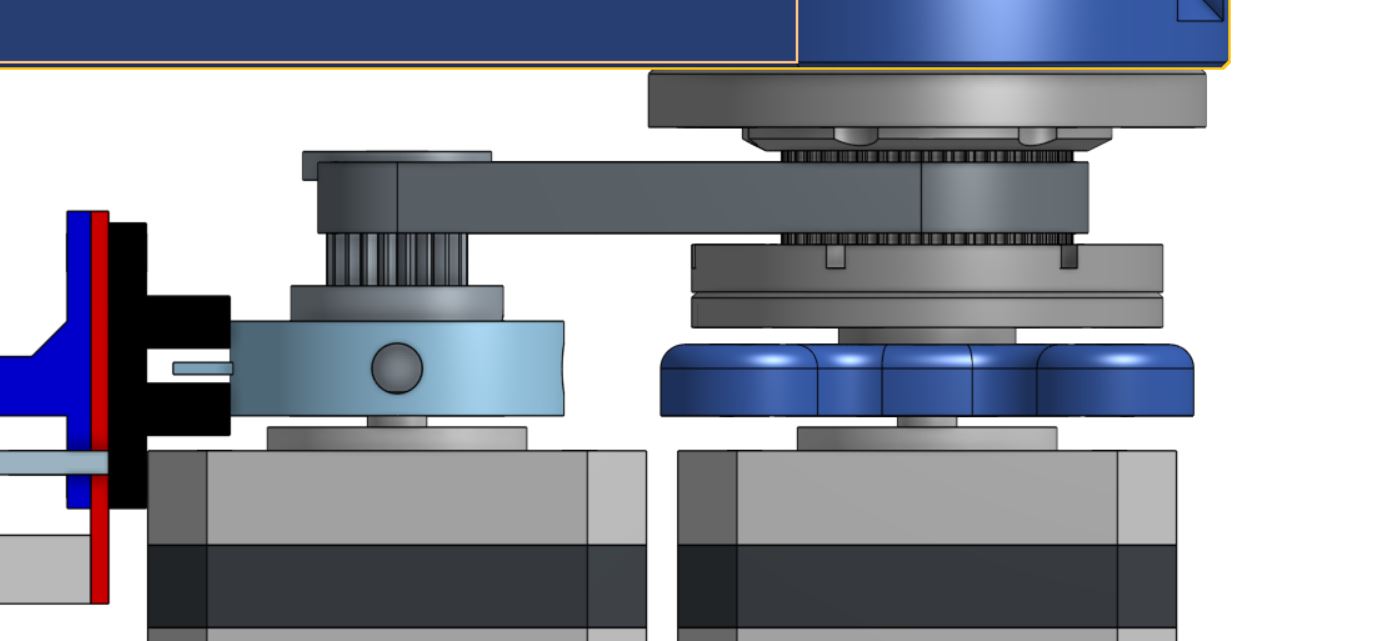
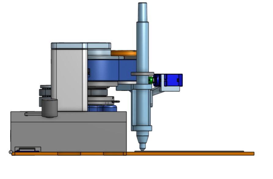
Final prototype-CAD
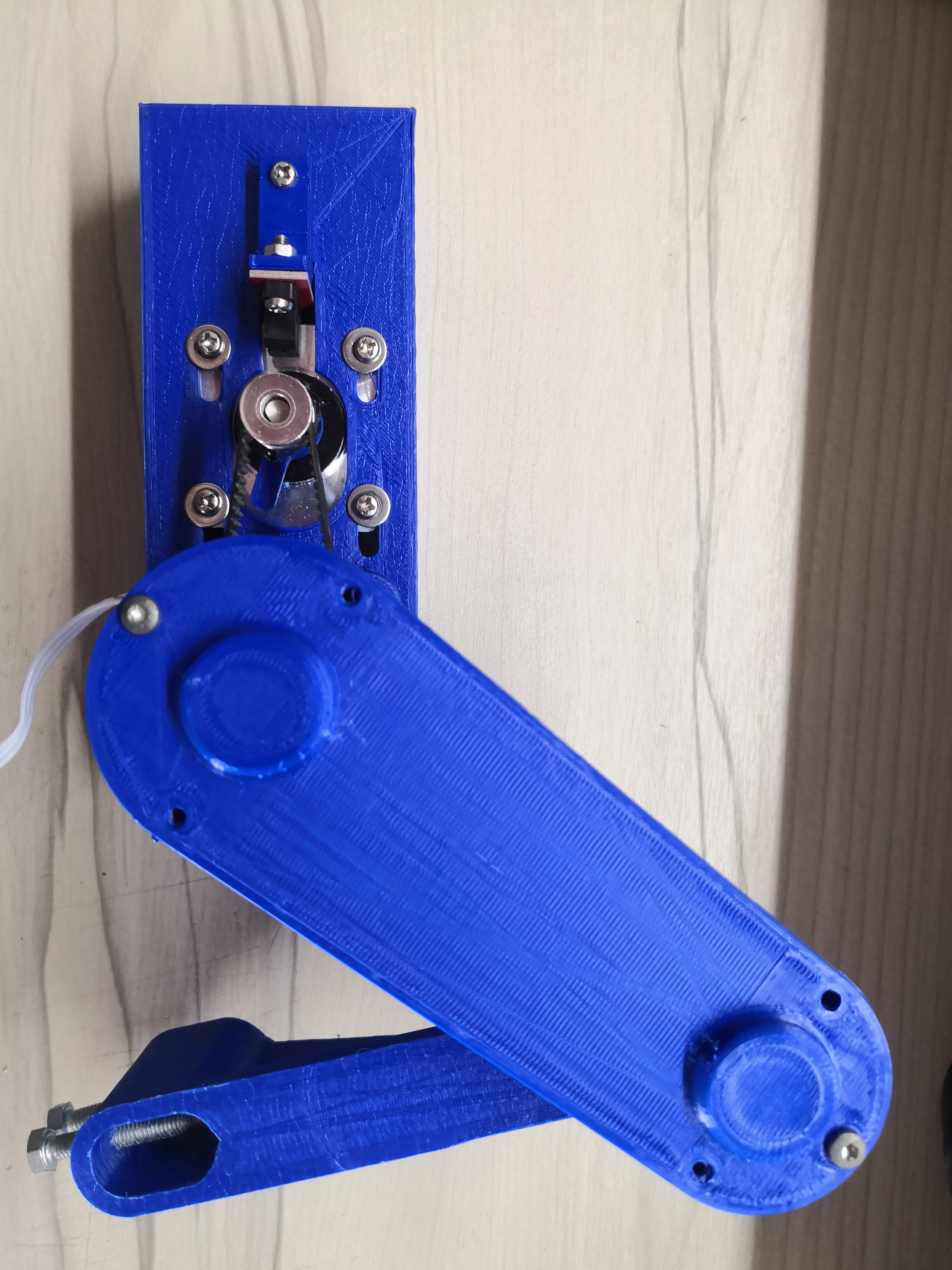
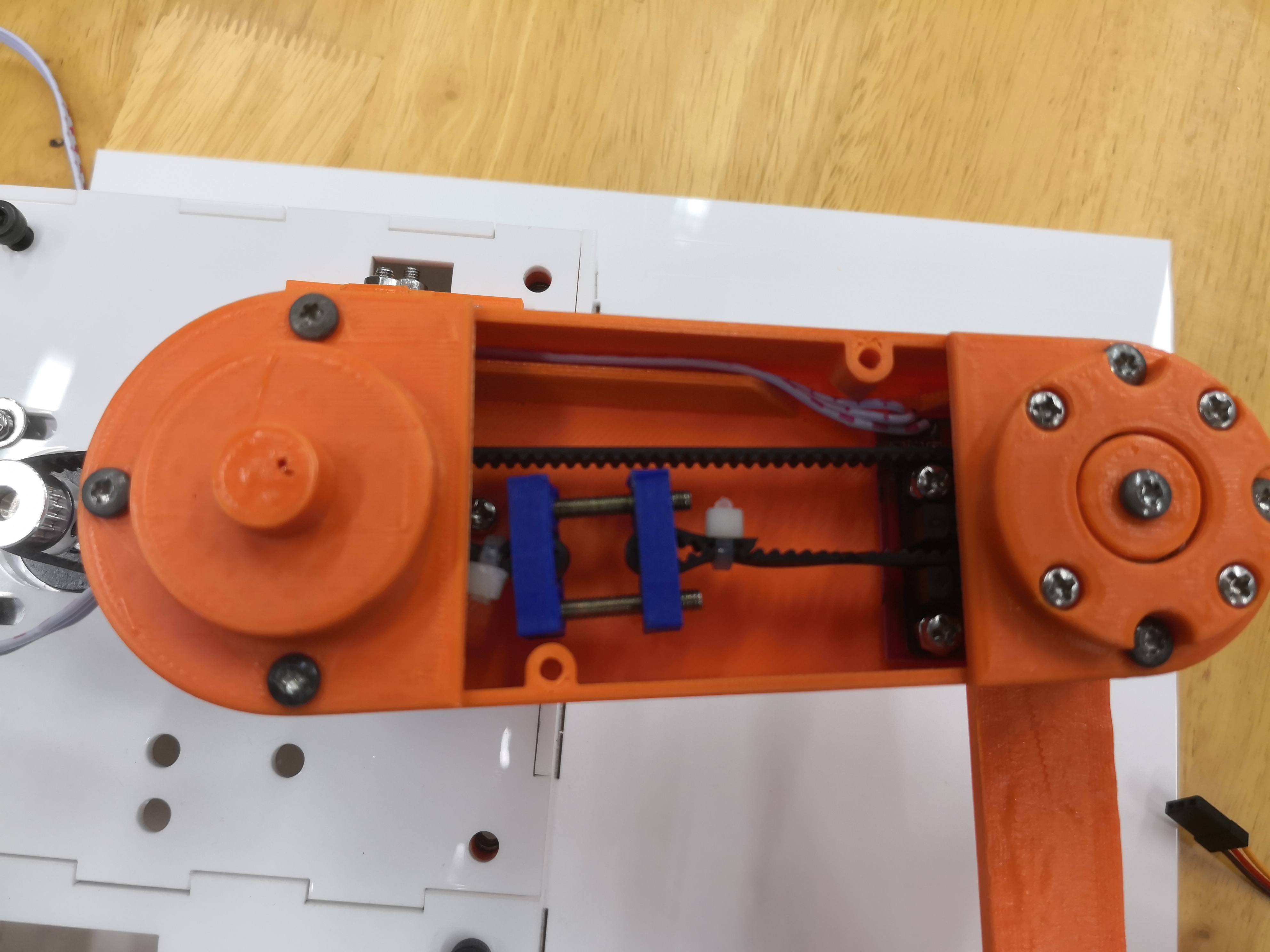
Below is the ful assembly of the pen plotter.
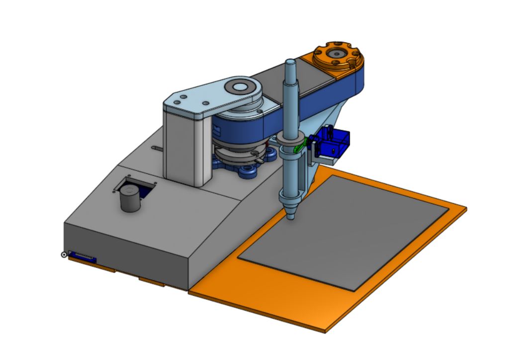
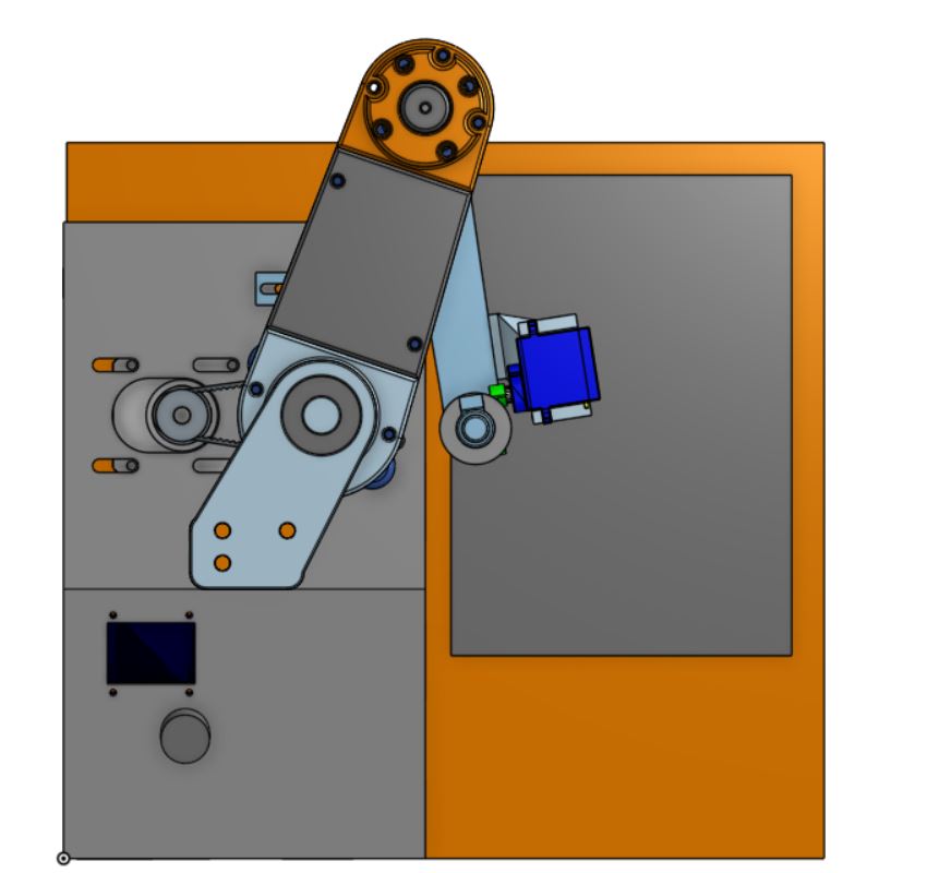
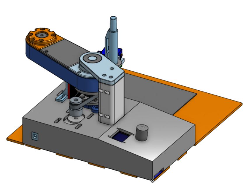
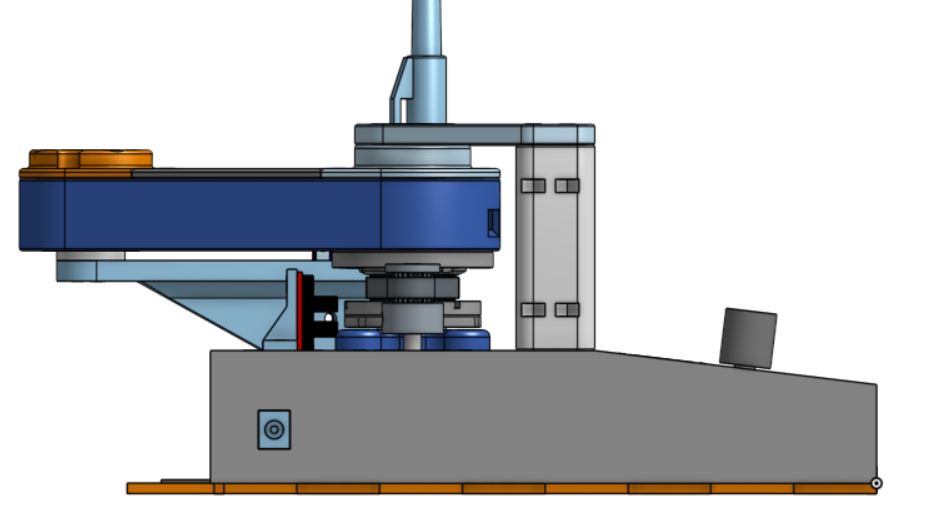
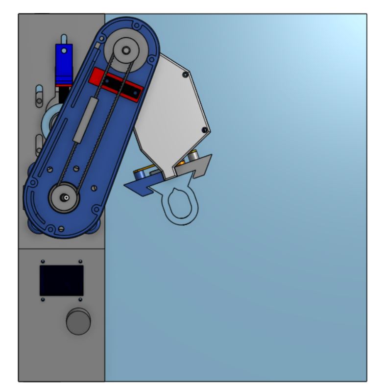
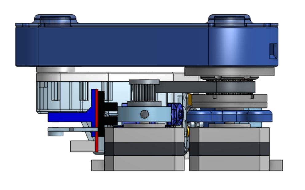
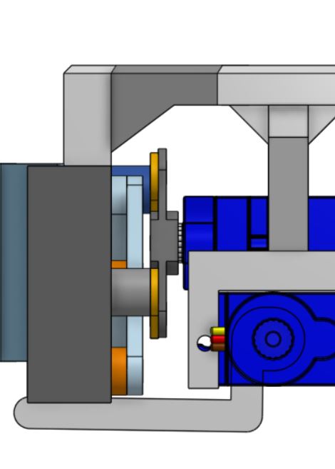
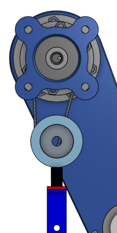
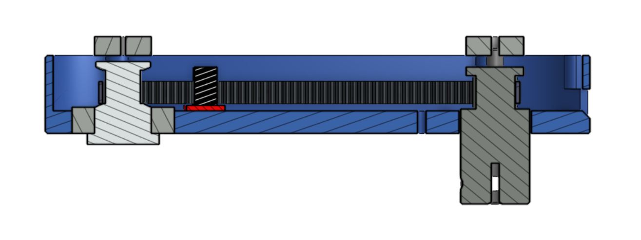
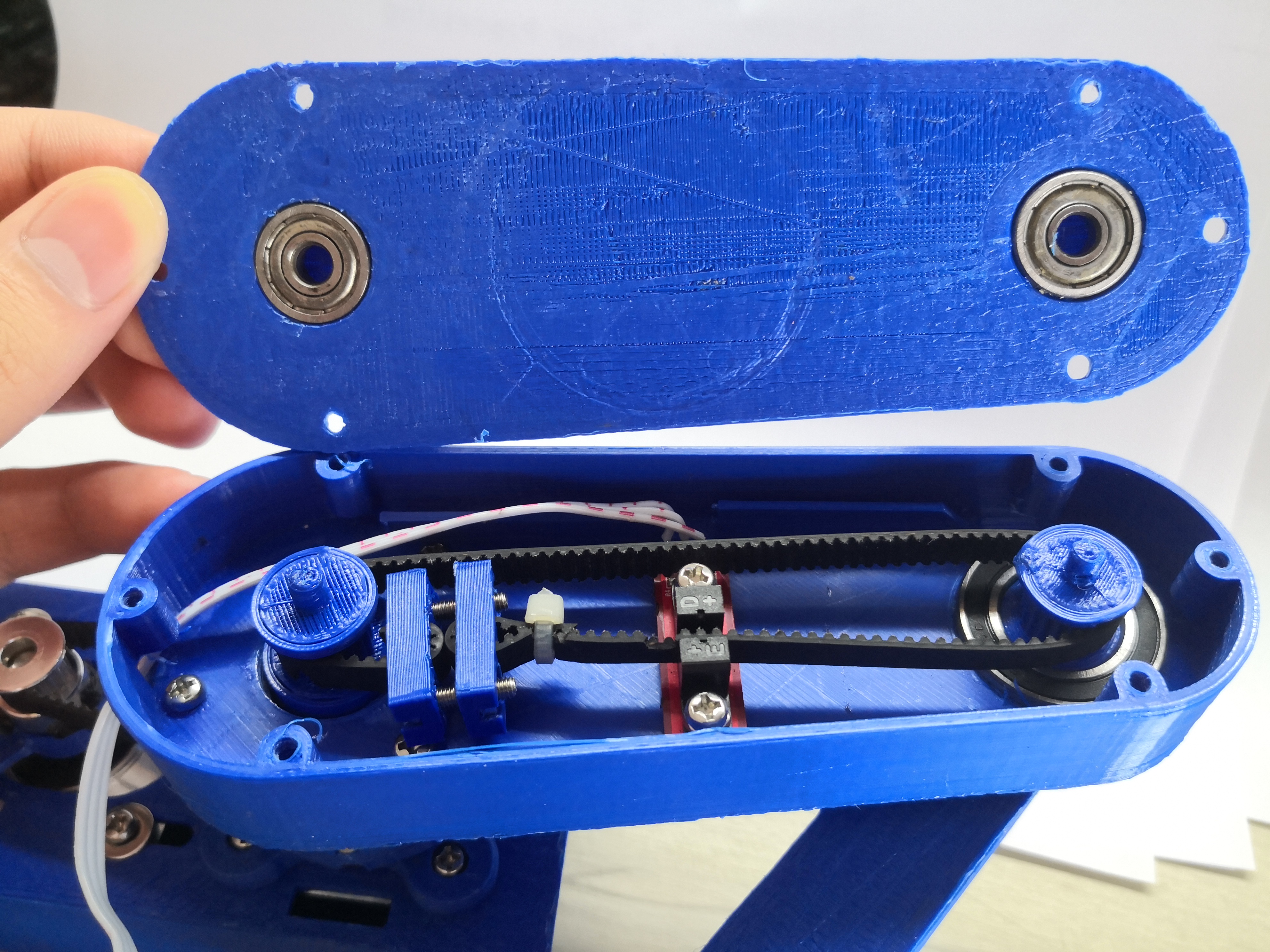
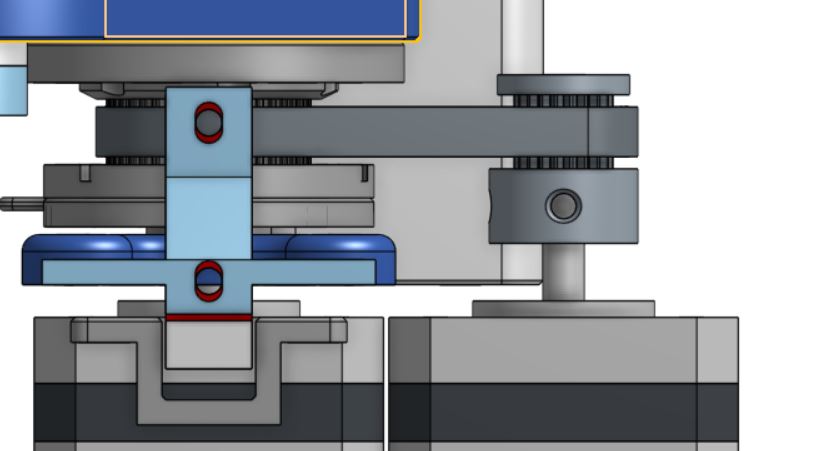
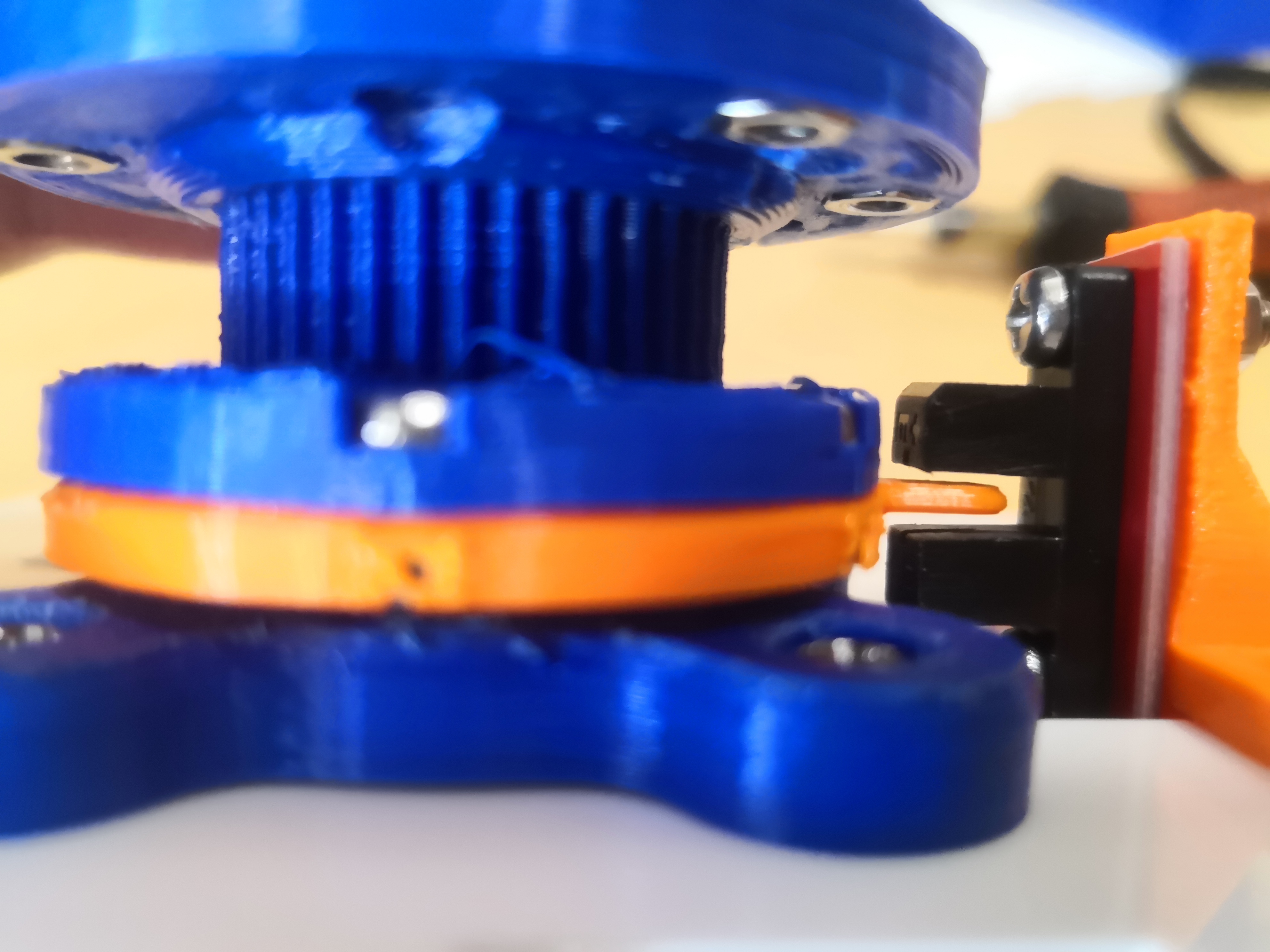
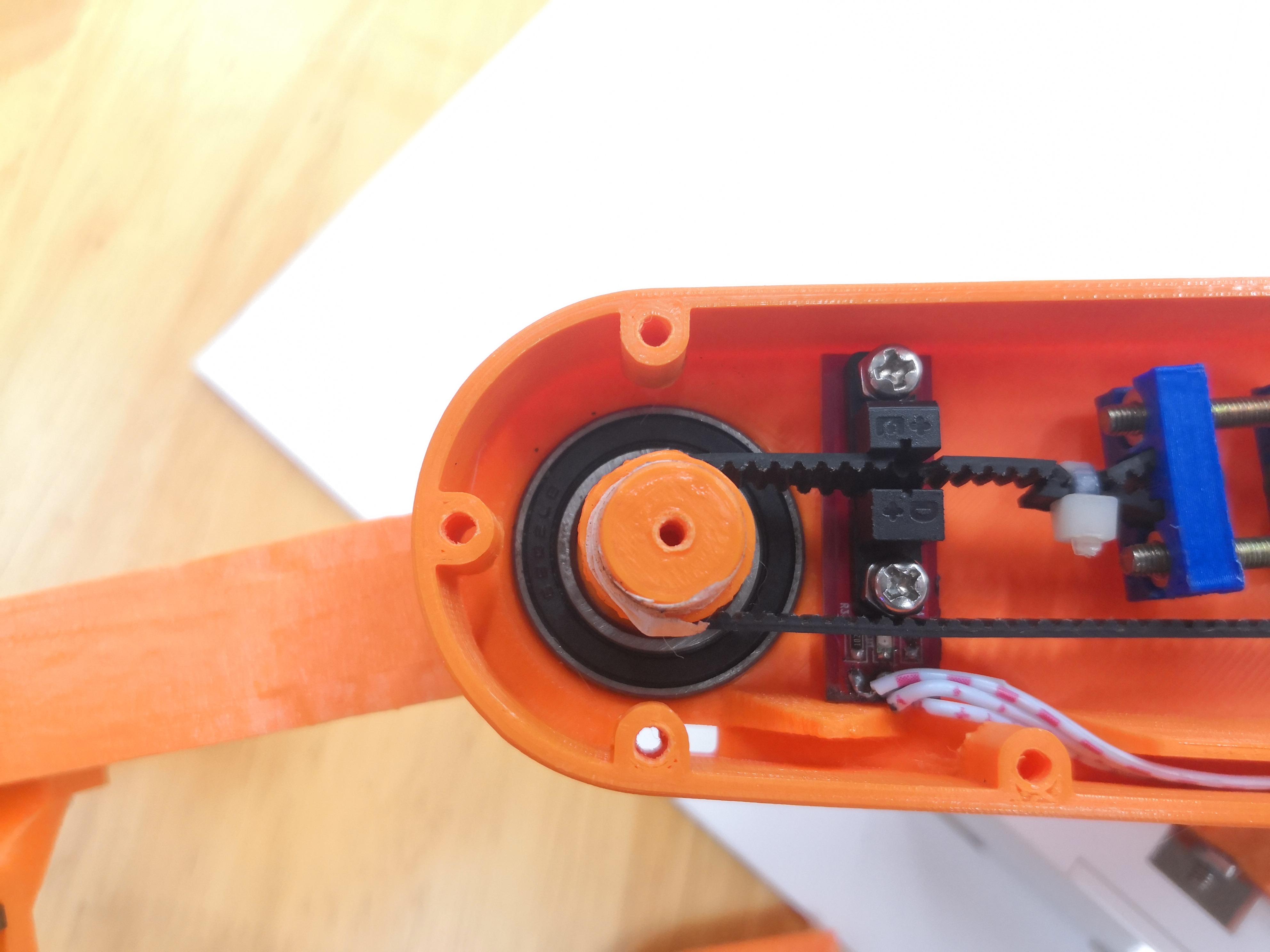
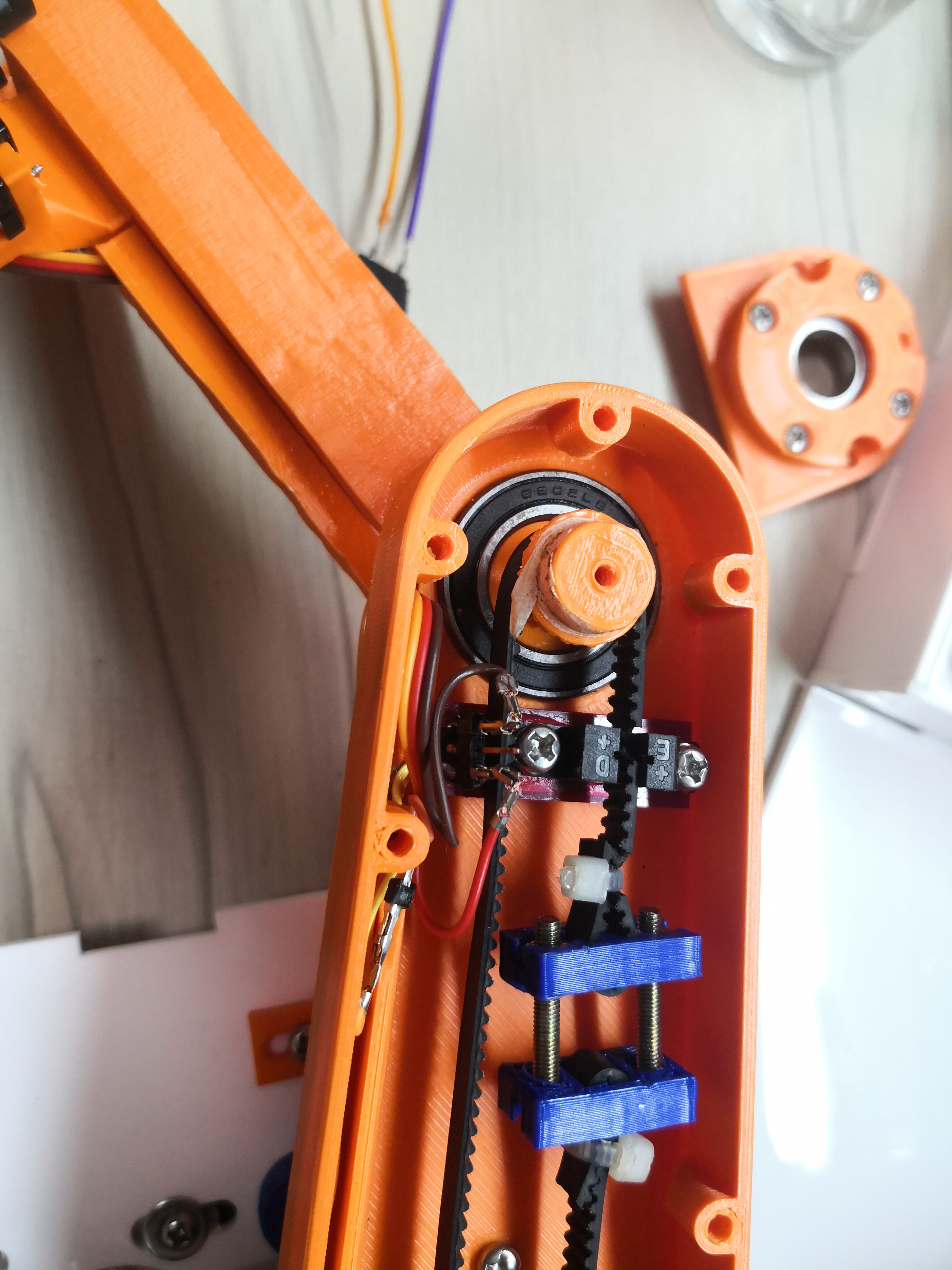
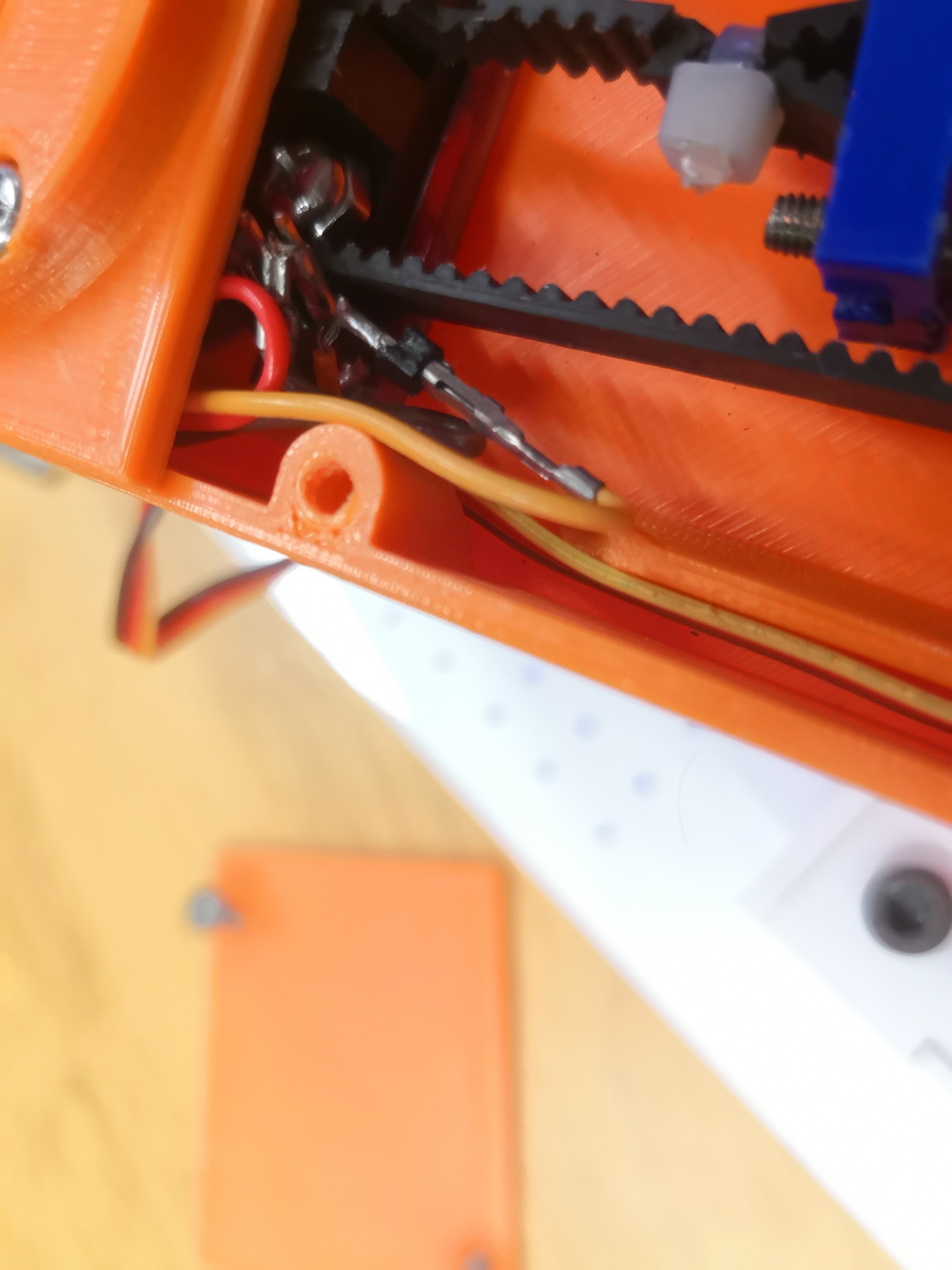
Close up of the pulley system.
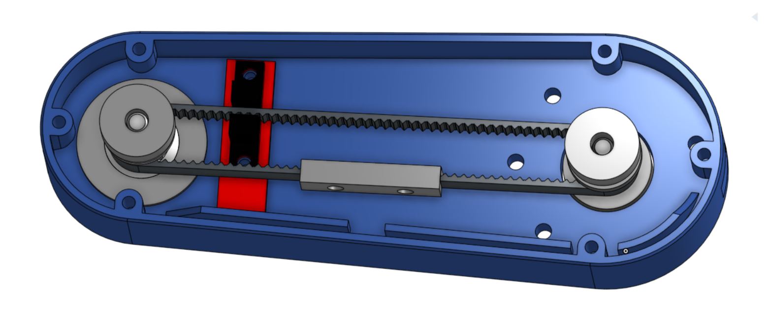
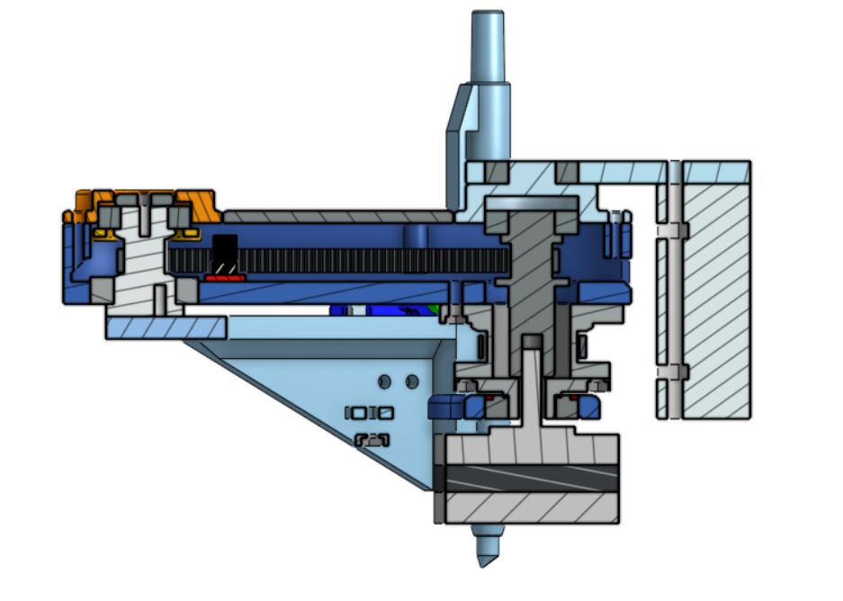
Inner arm internal pulley.
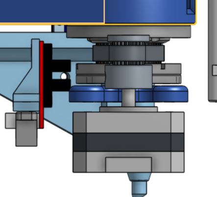
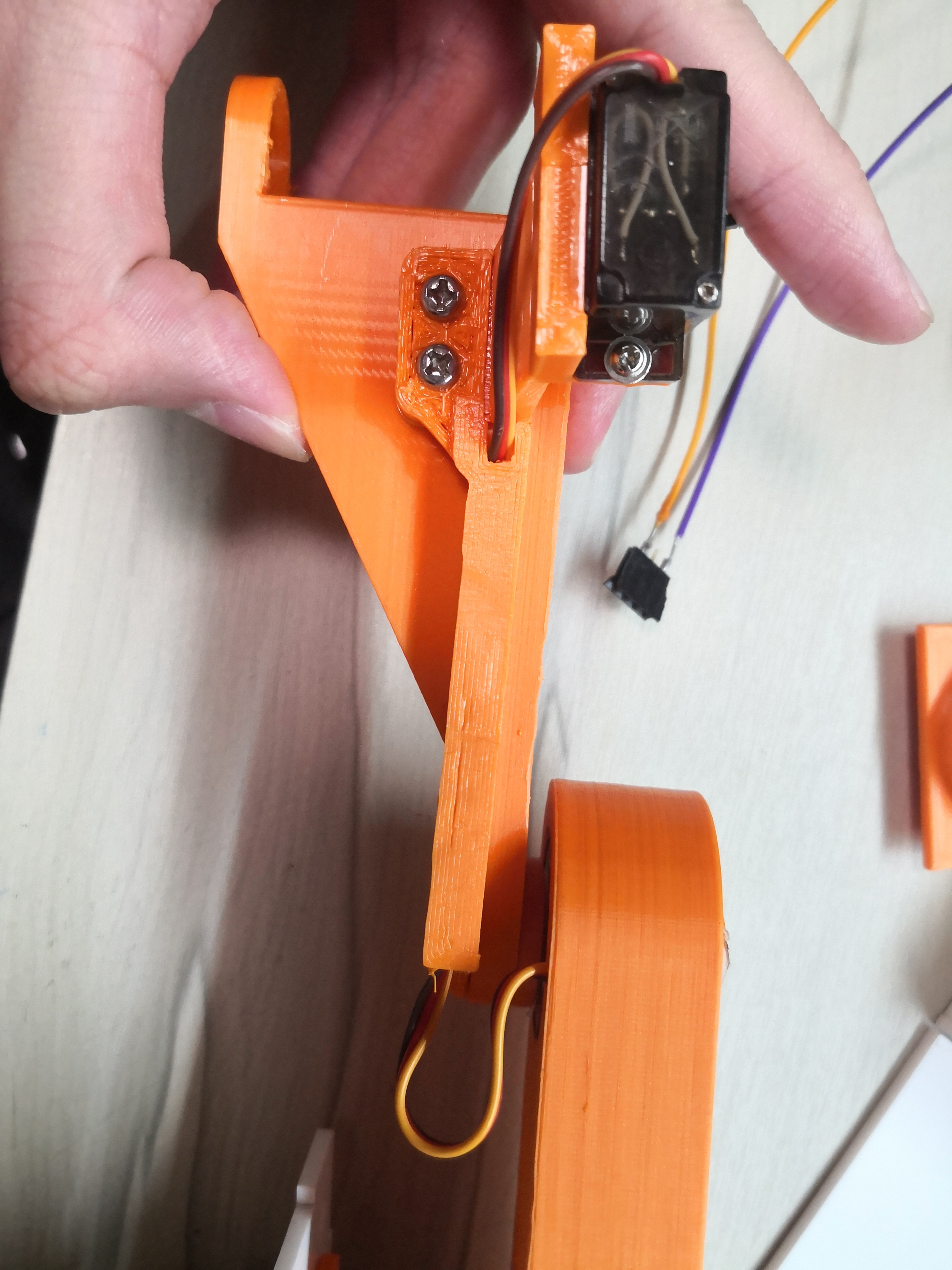
New, simple servo arm.
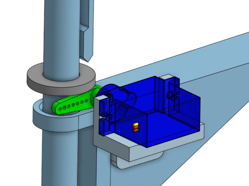
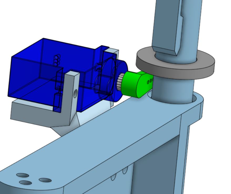
Click here to view the CAD model.
Final prototype-BOM
| N.O. | Part description | Qty |
|---|---|---|
| 1 | Arduino Nano | 1 |
| 2 | MG90 Servo motor | 1 |
| 3 | Optical sensor | 2 |
| 4 | NEMA 17 Stepper motor | 2 |
| 5 | HR4988 driver | 2 |
| 6 | 5.5*2.1 Barrel jack | 1 |
| 7 | 12V 1A Power supply | 1 |
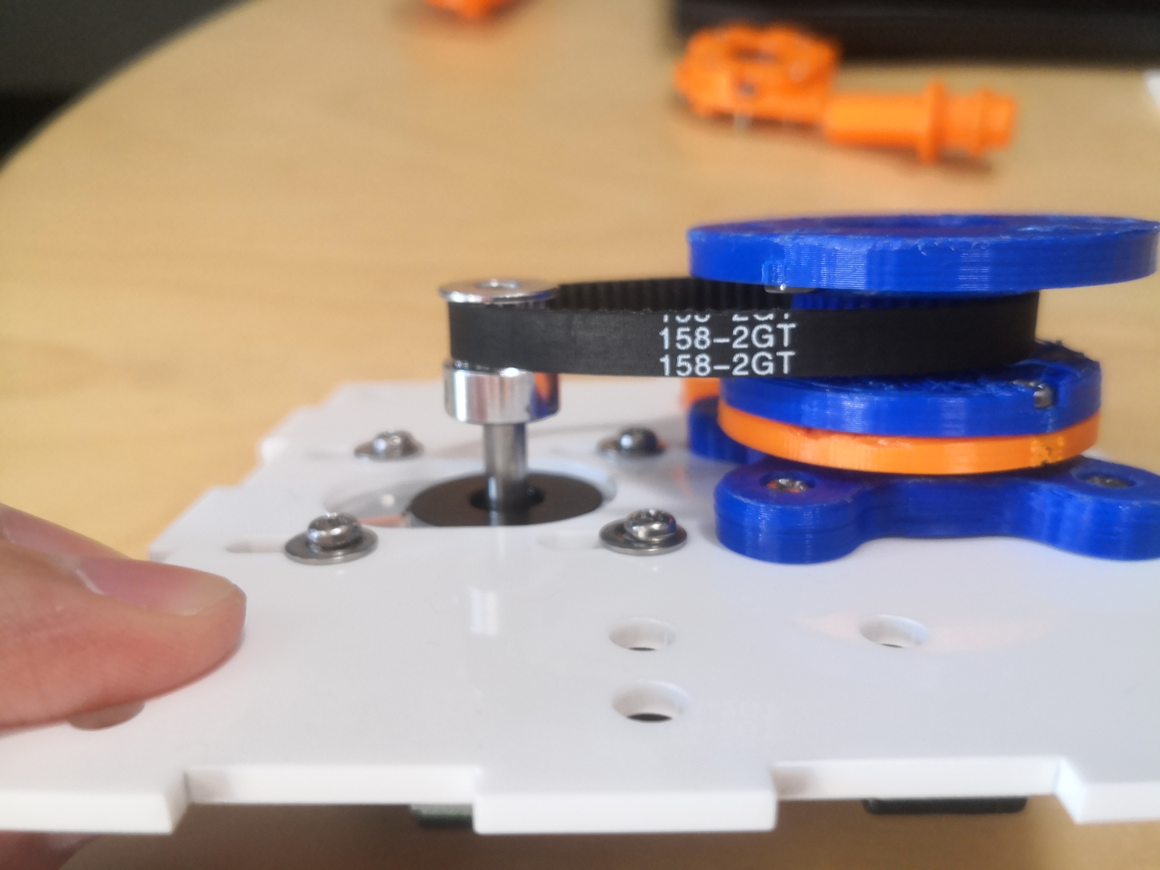
| 8 | GT2 timing belt, closed, 158mm, 6mm width | 1 |
| 9 | GT2 pulley, 16 tooth, 6mm width, 5mm bore | 1 |
| 10 | GT2 timing belt, open, 250mm min, 6mm width | 1 |
| 11 | M3x7mm screw | 6 |
| 12 | M4 washer | 4 |
| 13 | M3*12mm screw | 18 |
| 14 | M3*5mm screw | 5 |
| 15 | M3 nut | 19 |
| 16 | #4x8mm self-tapping screw | 8 |
| 17 | M5x20mm screw | 2 |
| 18 | 6901 12x24x6mm bearing | 5 |
| 19 | 61902 16x28x7 bearing | 1 |
| 20 | 47uF capacitor 50V | 4 |
| 21 | 7805 voltage regulator | 1 |
| 22 | 1X40 Female header | 2 |
| 23 | M4*20mm | 8 |
| 24 | M4 nut | 8 |
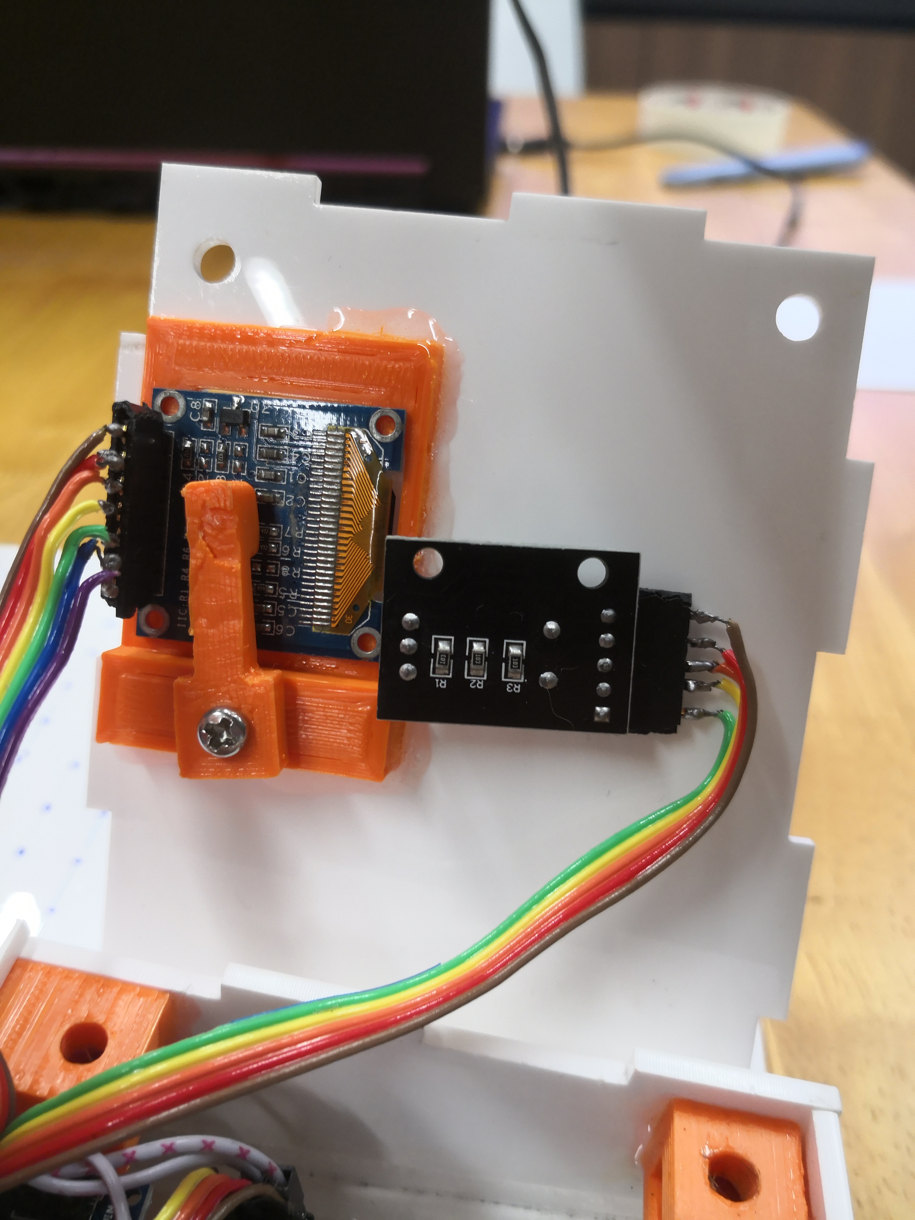
| 25 | OLED screen | 1 |
| 26 | Micro SD card reader | 1 |
| 27 | Rotory encoder | 1 |
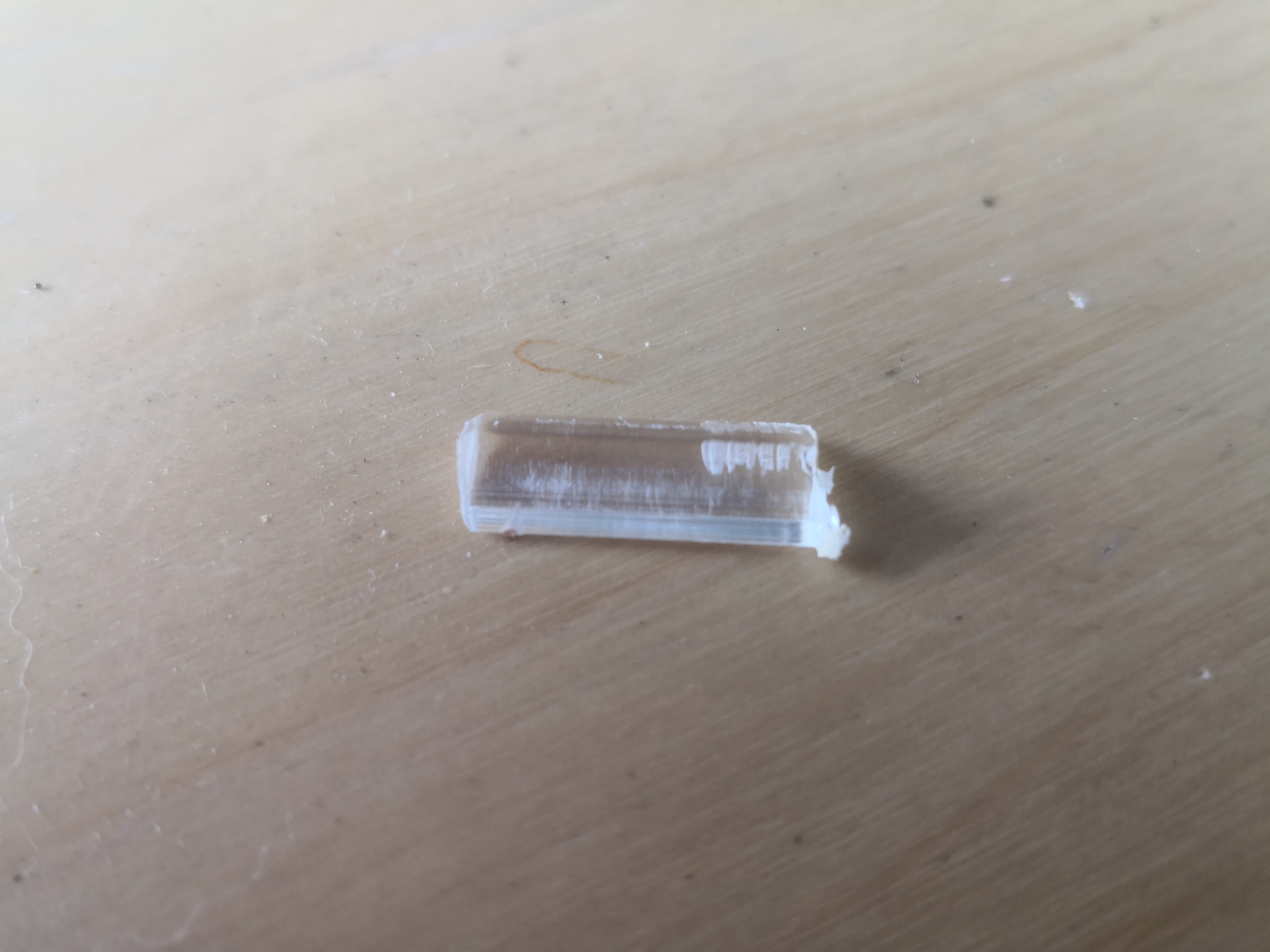
Final prototype-3D printing
The part is printed on a 3D printer.
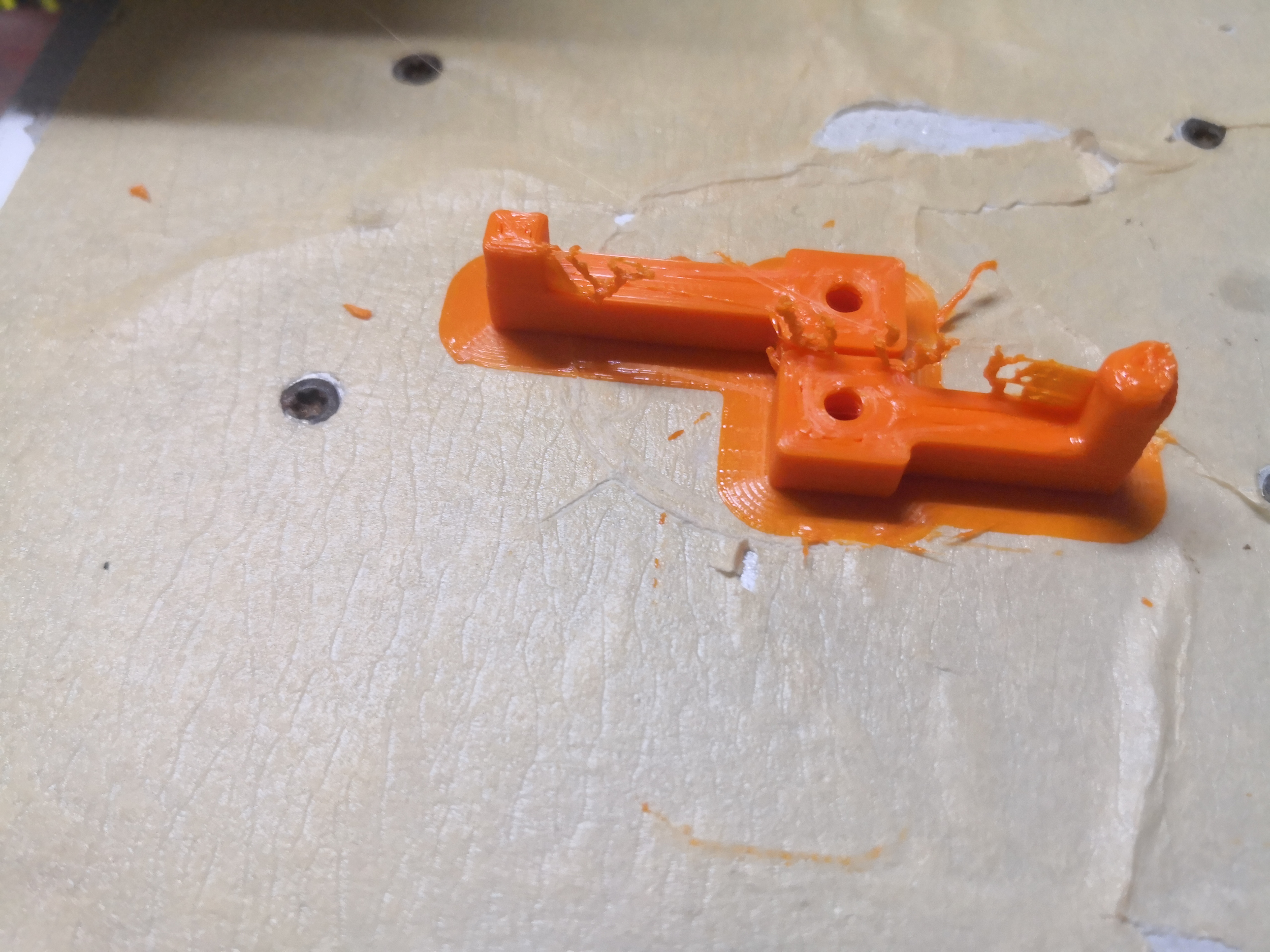
The 3d printed part is scraped off the bed.
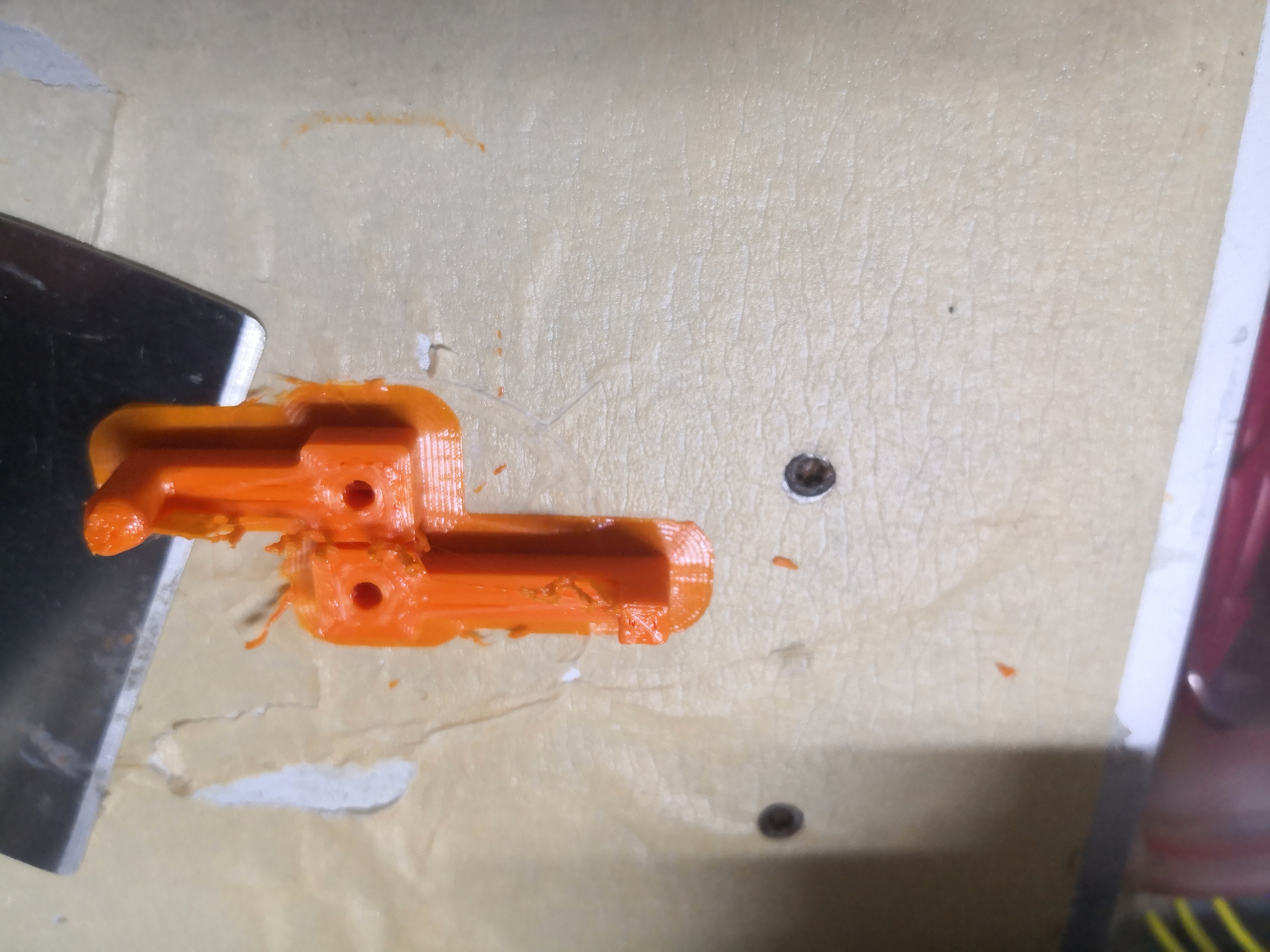
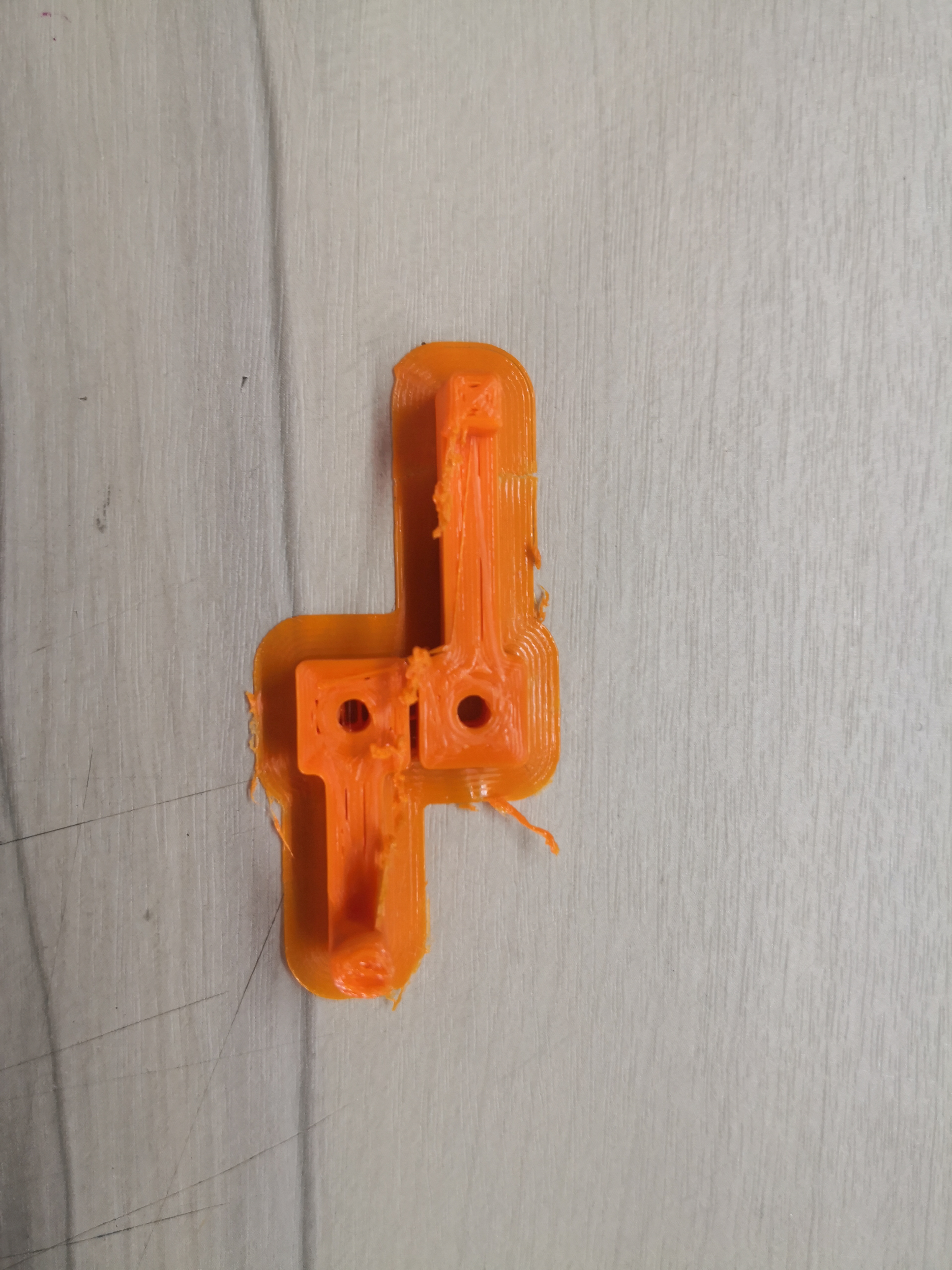
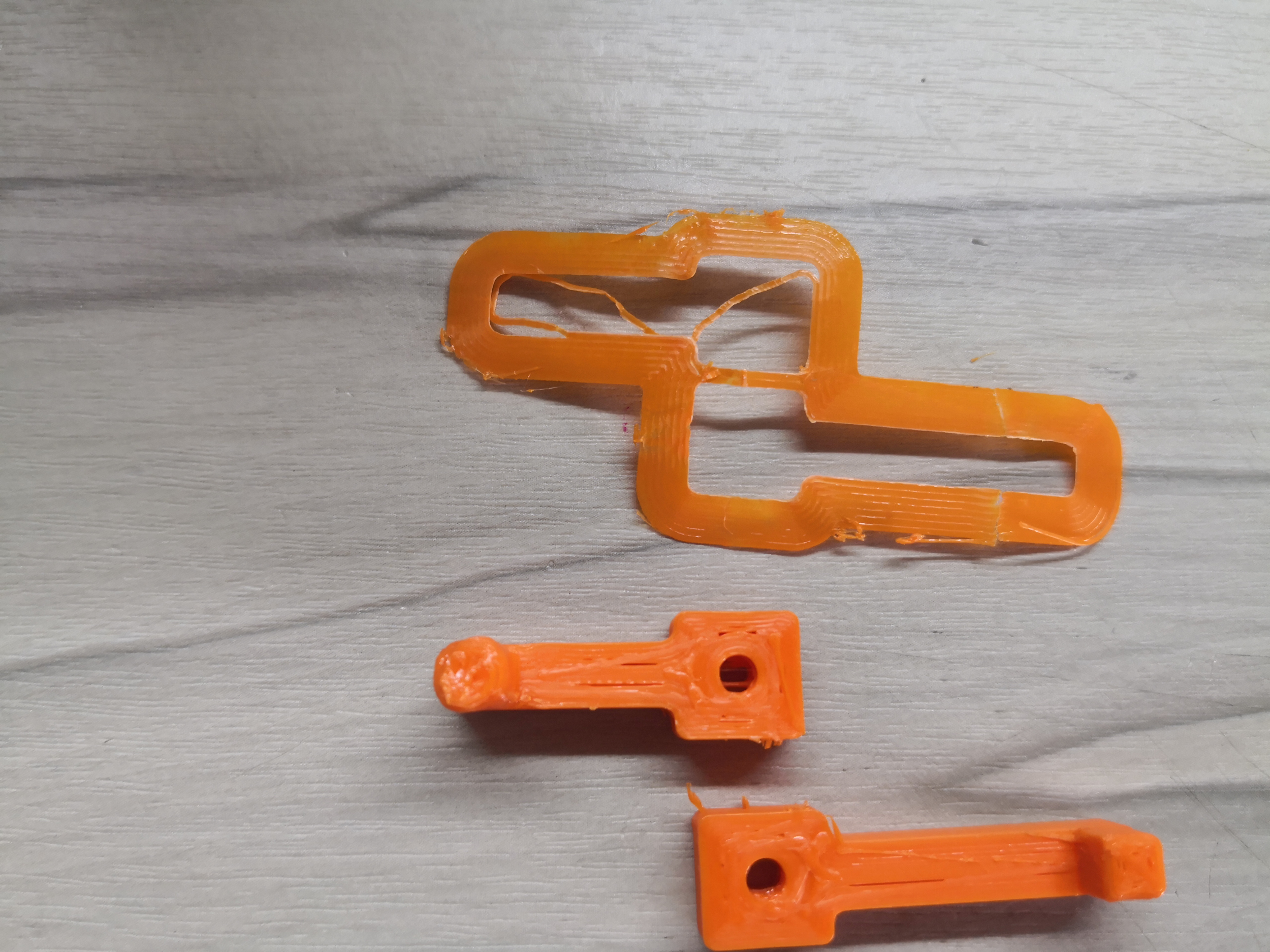
The brim and support material is removed.
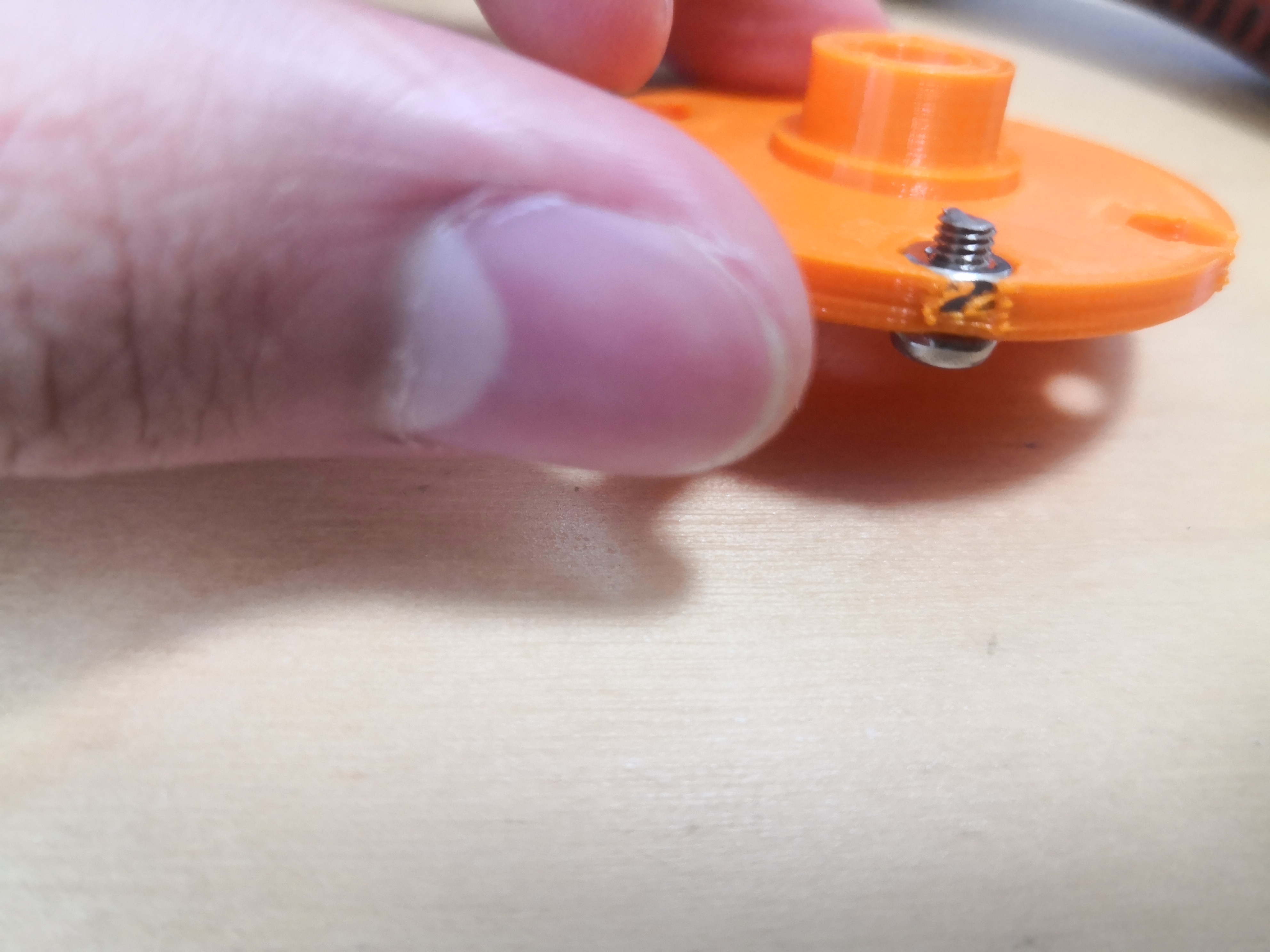
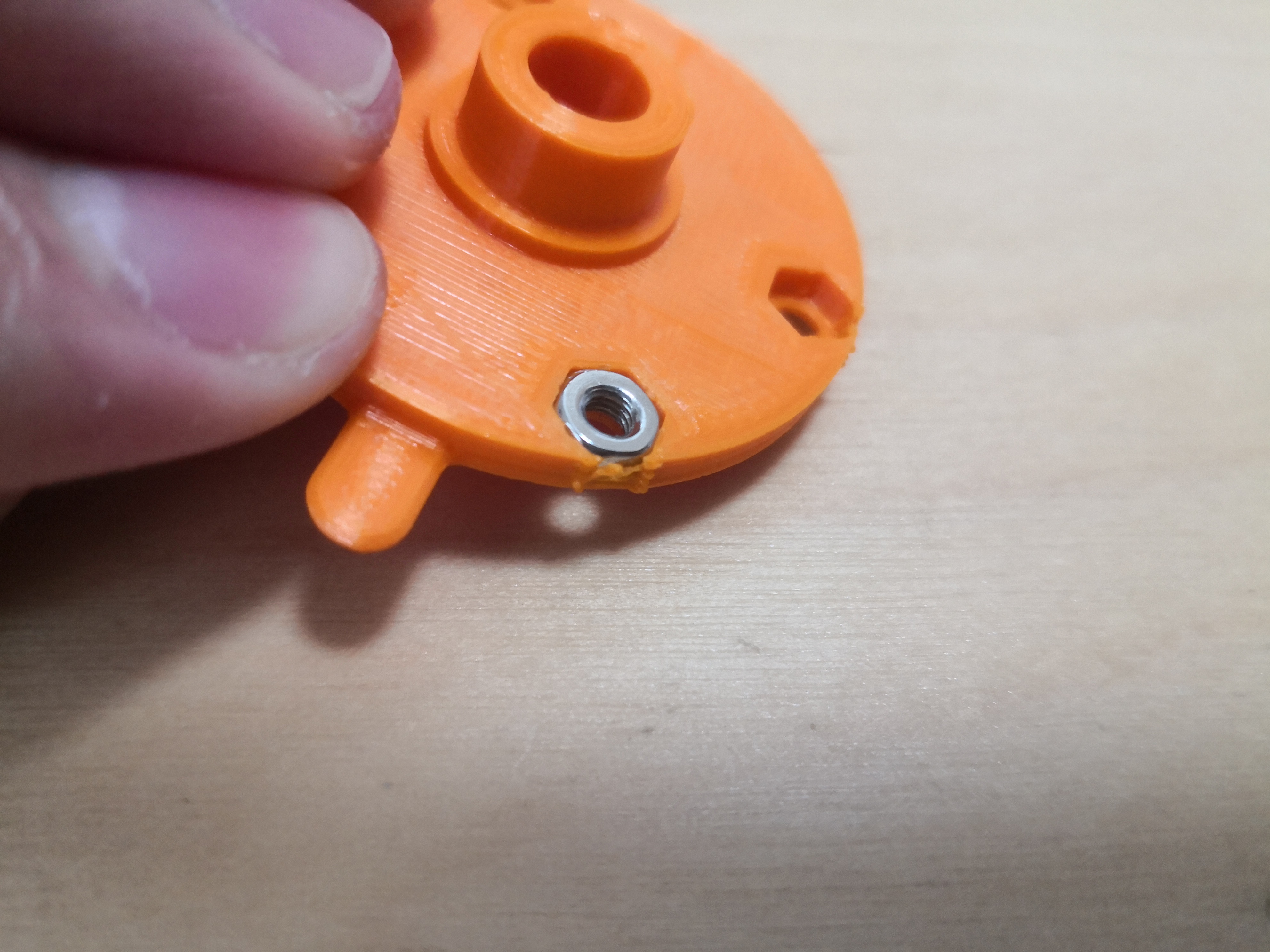
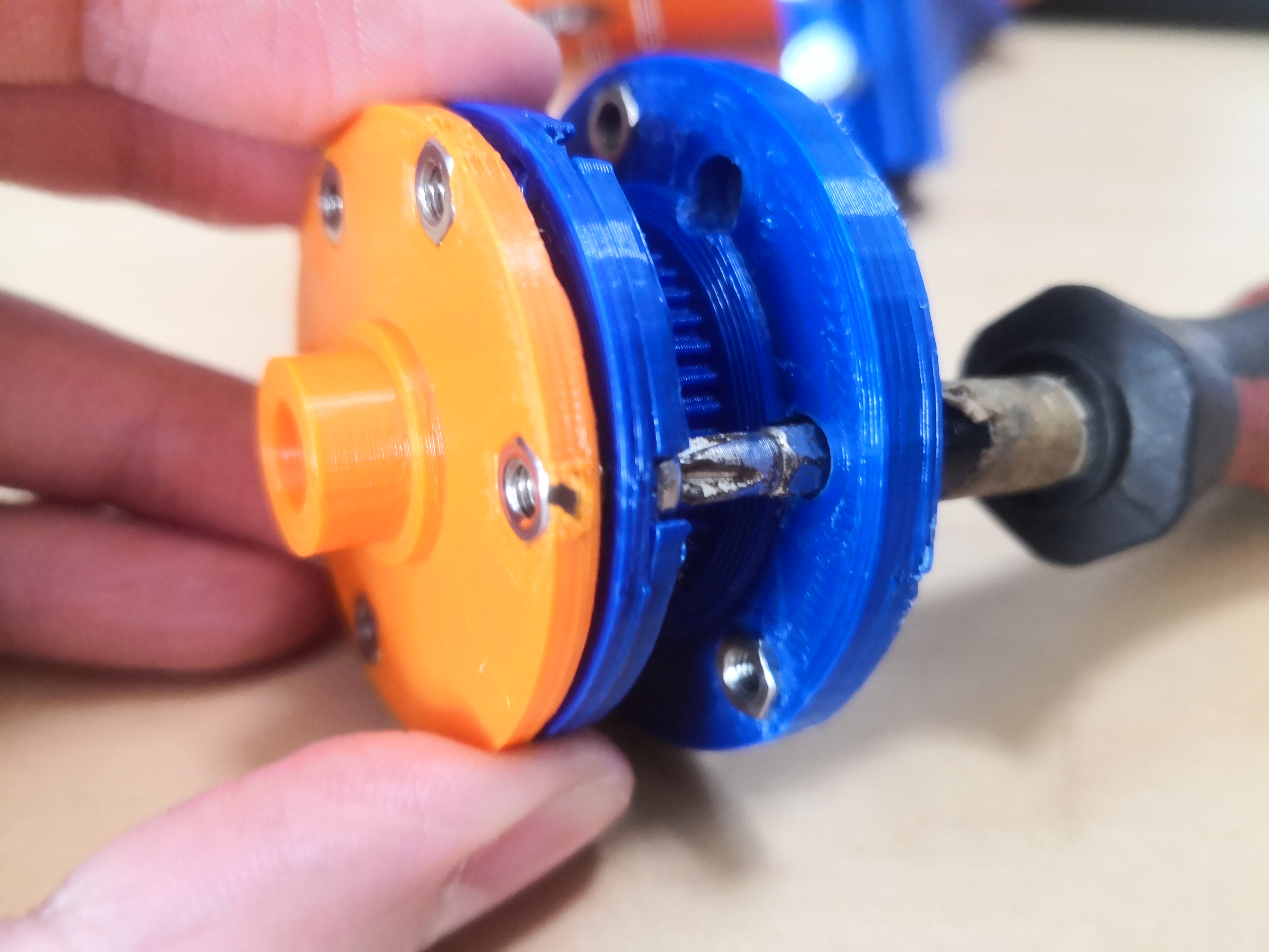
A nut is embeded into 3D printed parts with a soldering iron.
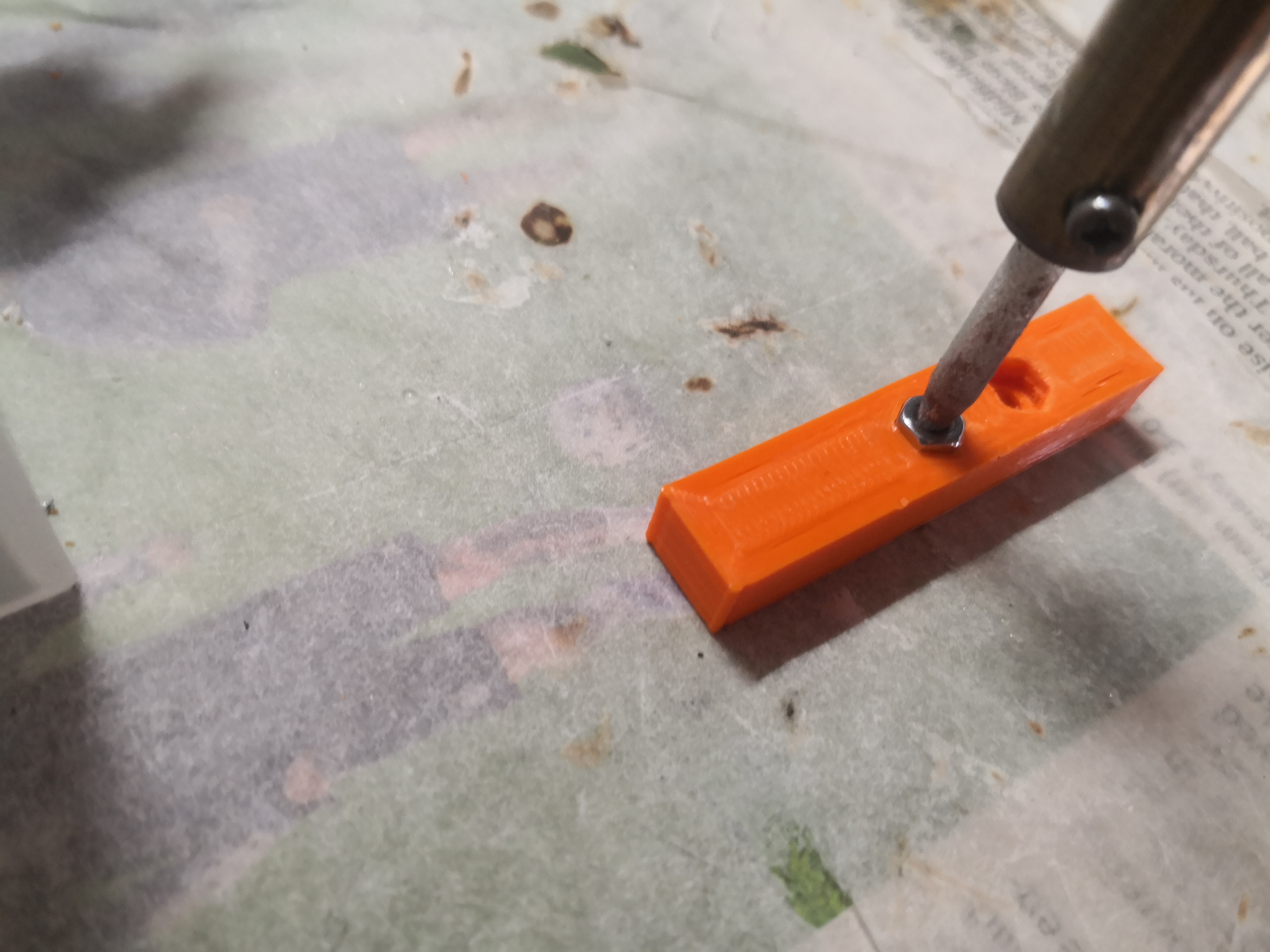
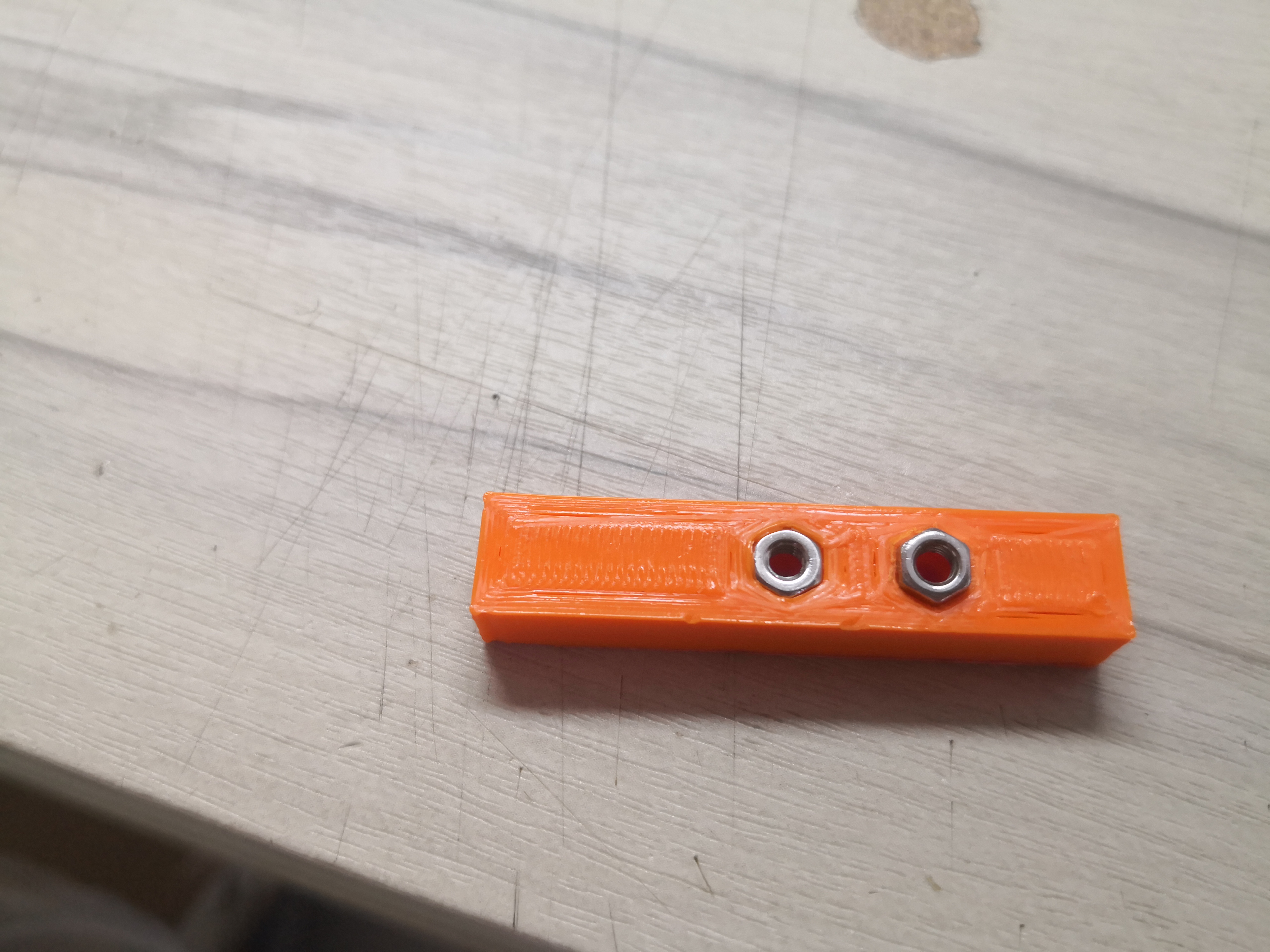
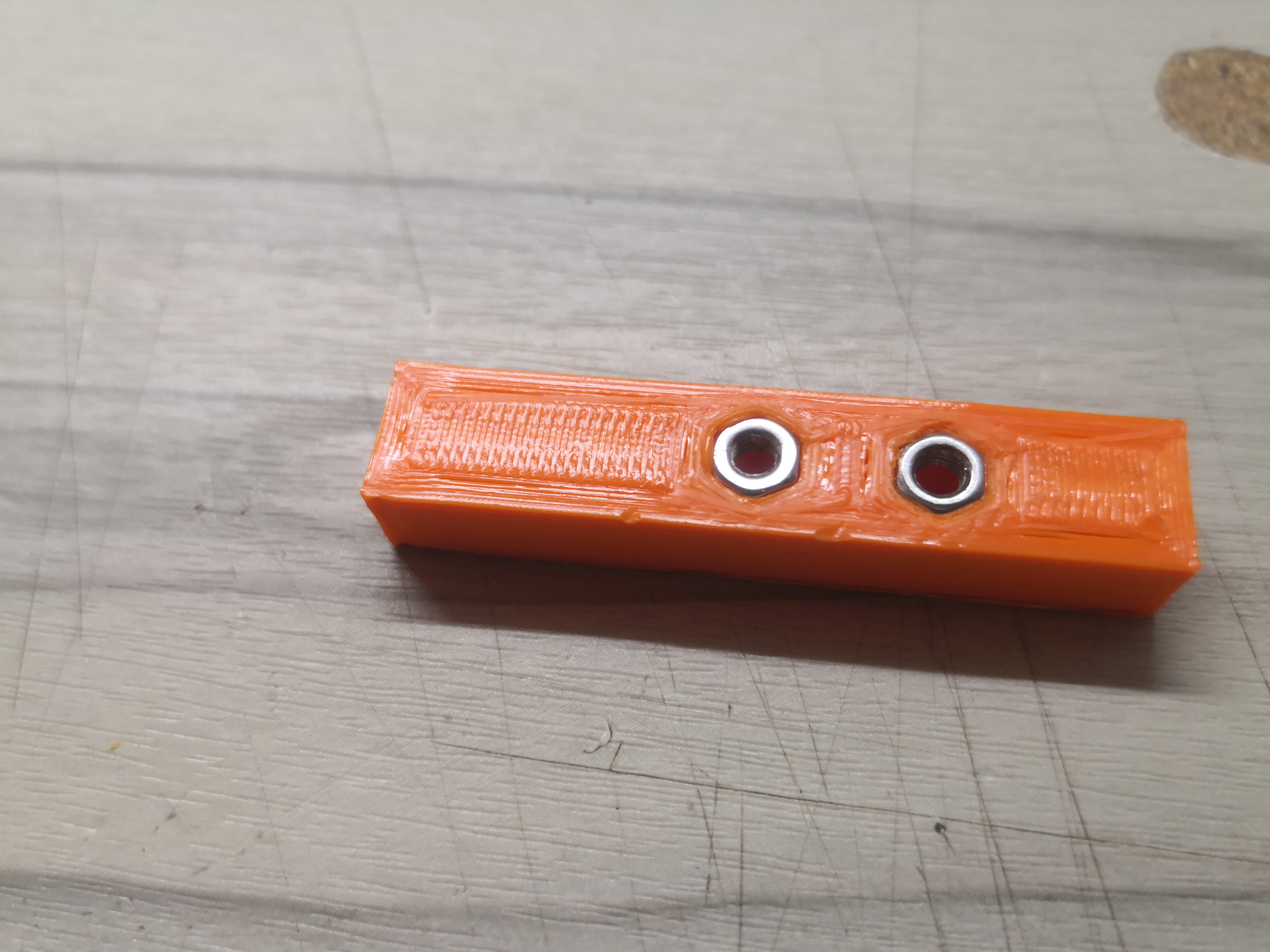
Nuts are pressed in with a screw.
Parts are quled to the acyrlic.

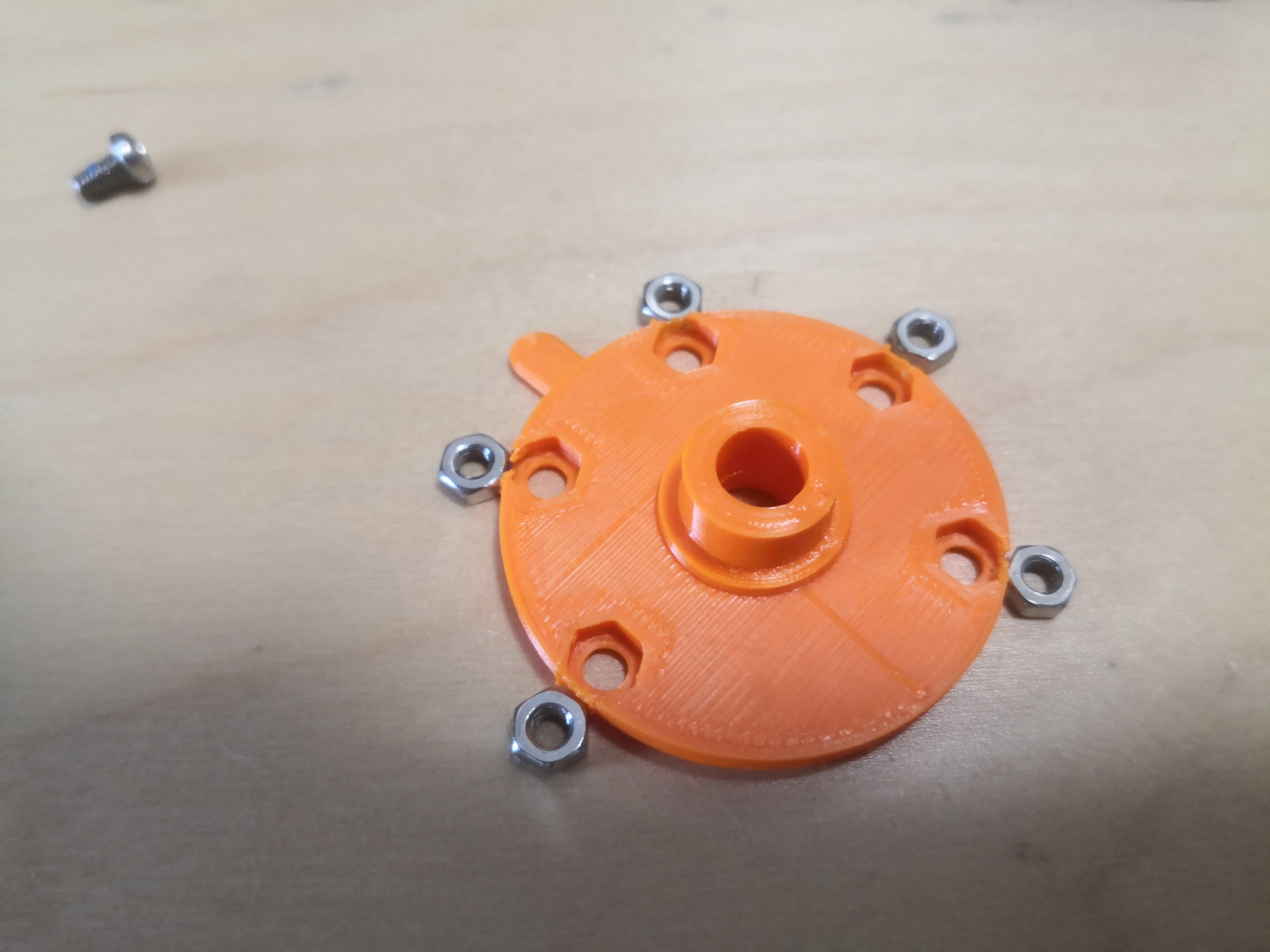
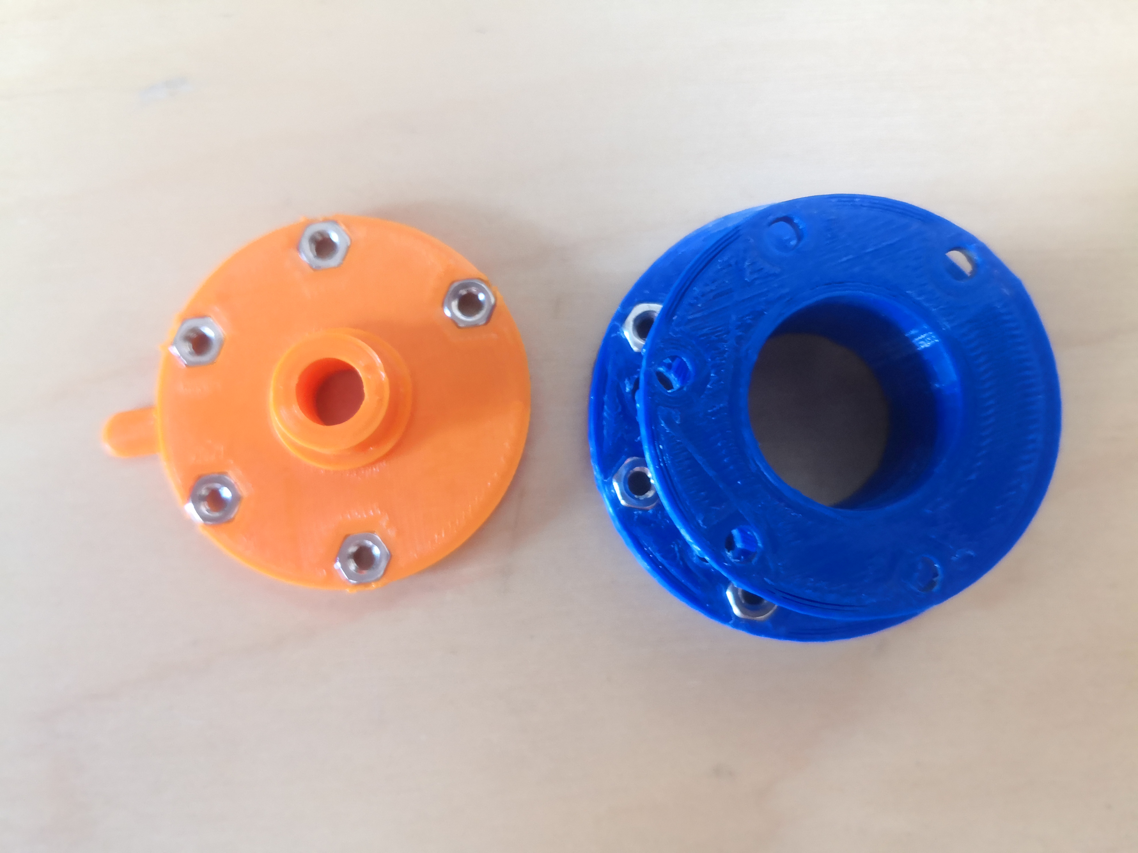
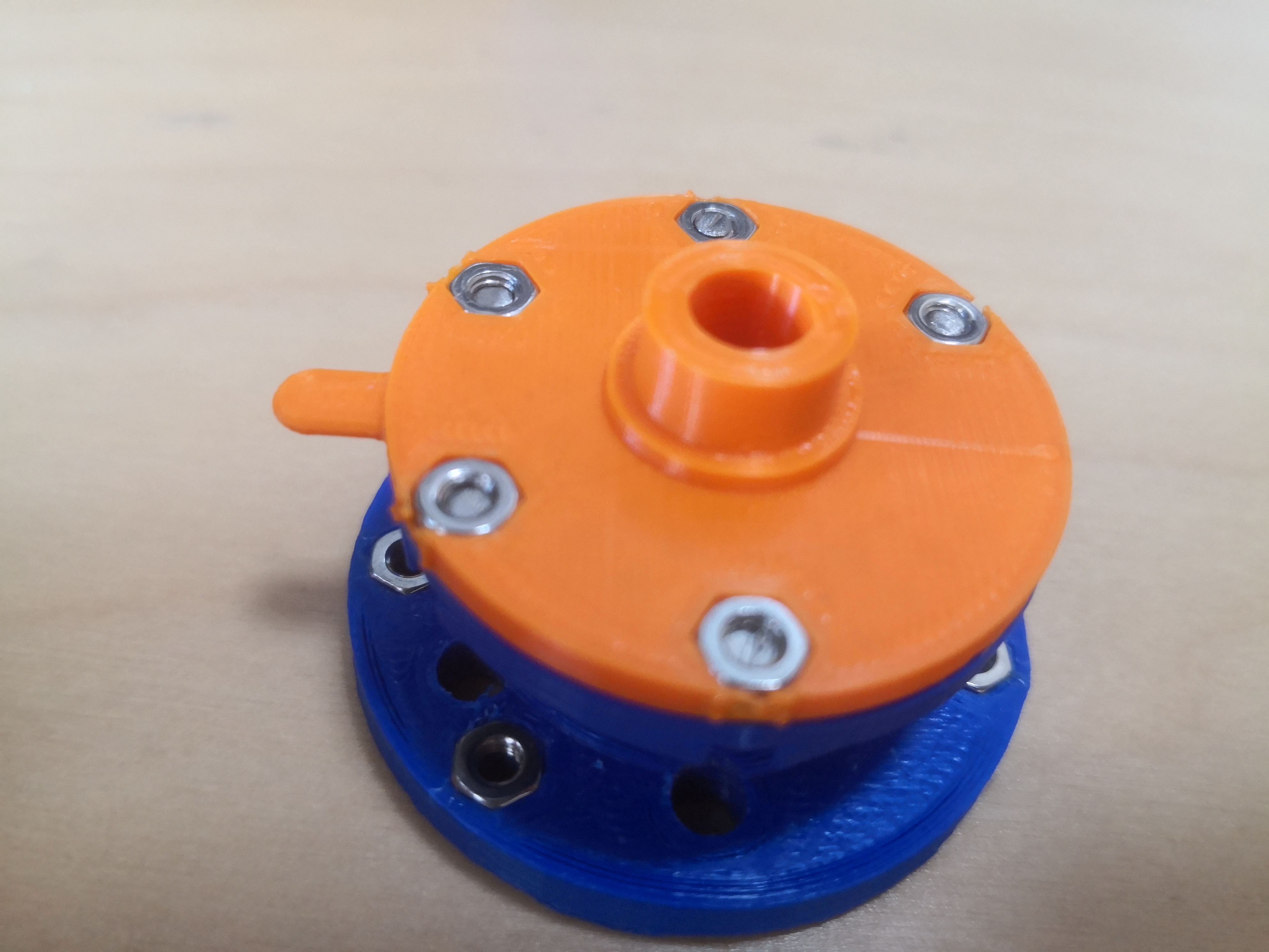
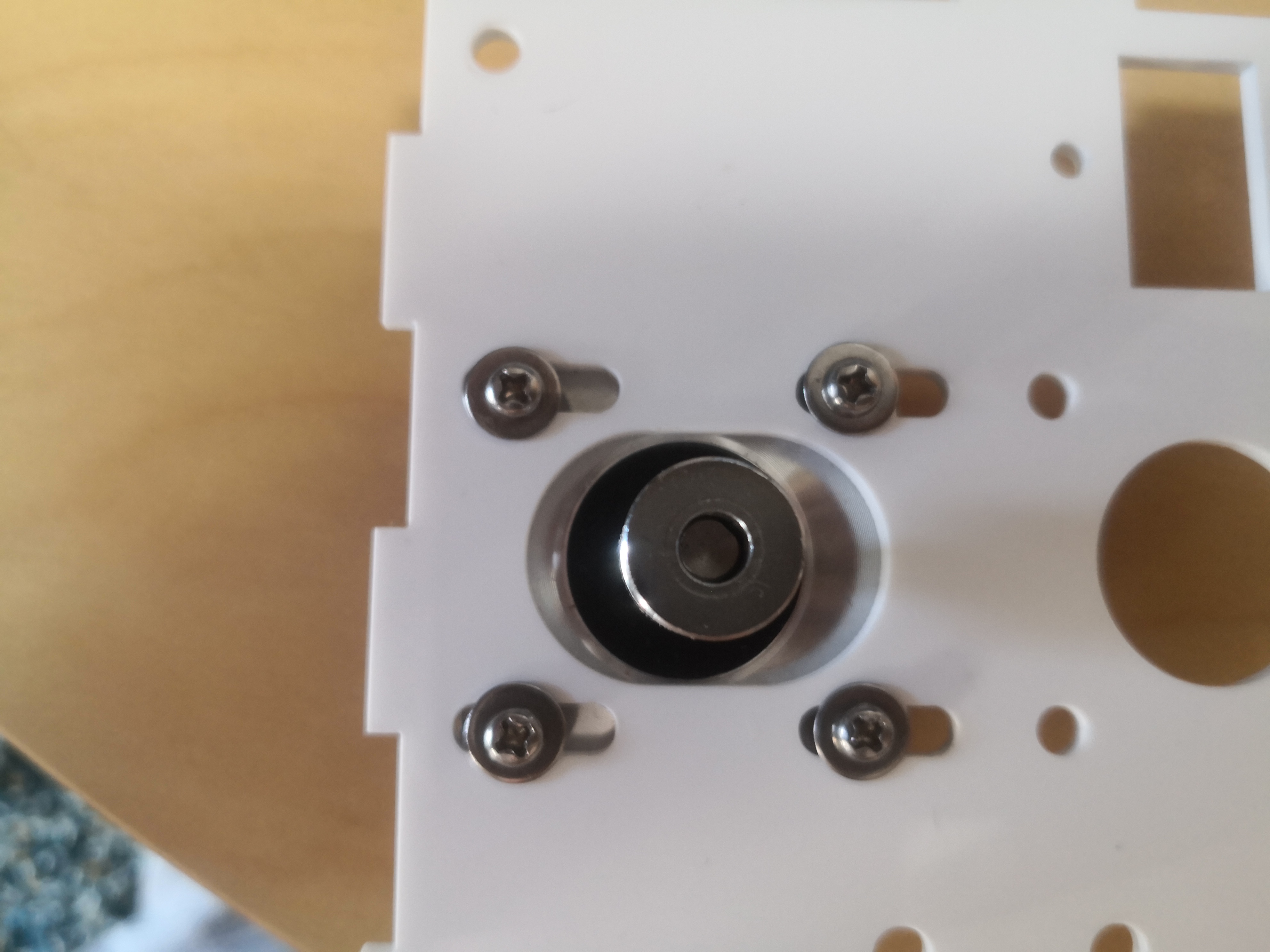
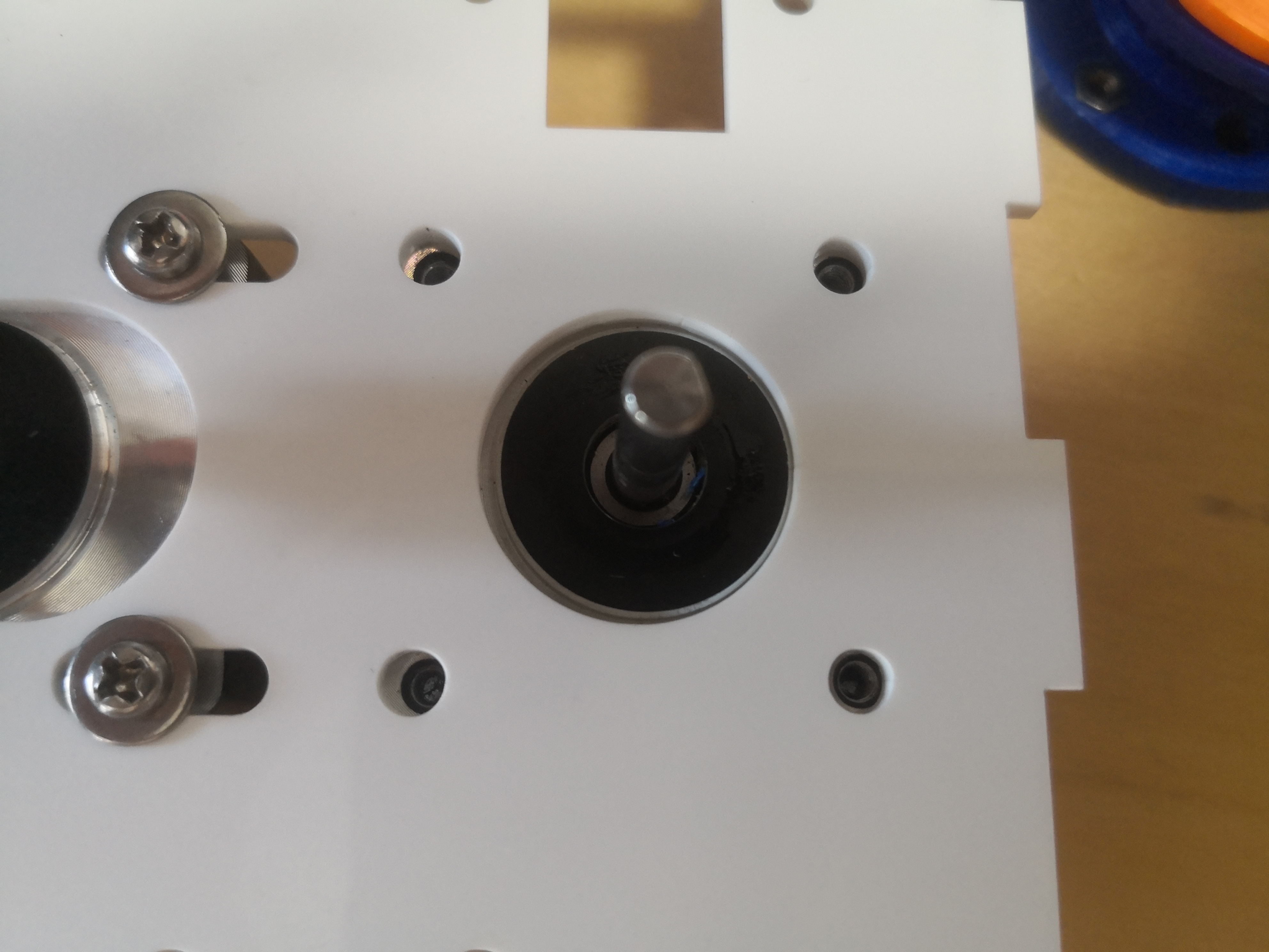
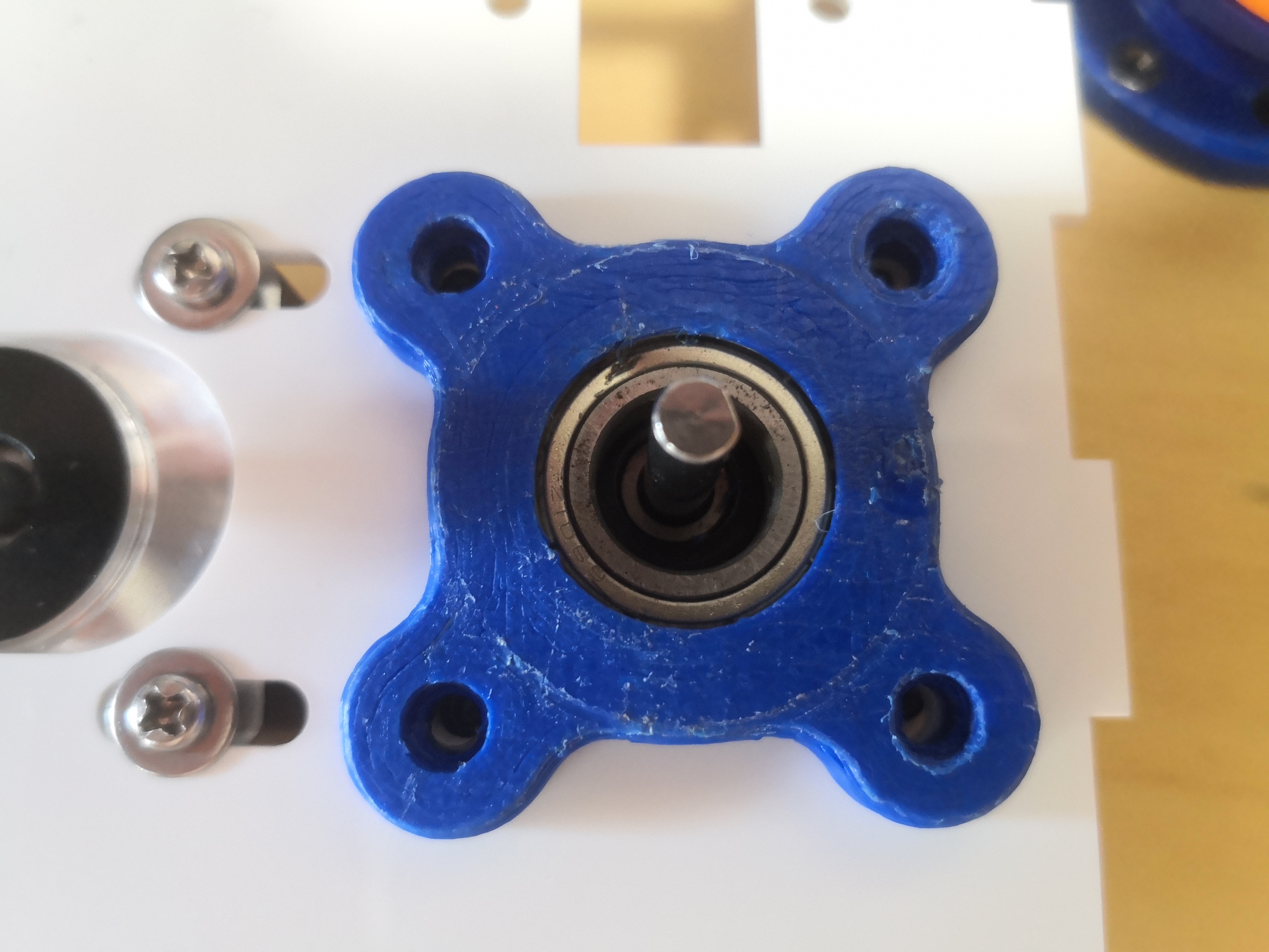
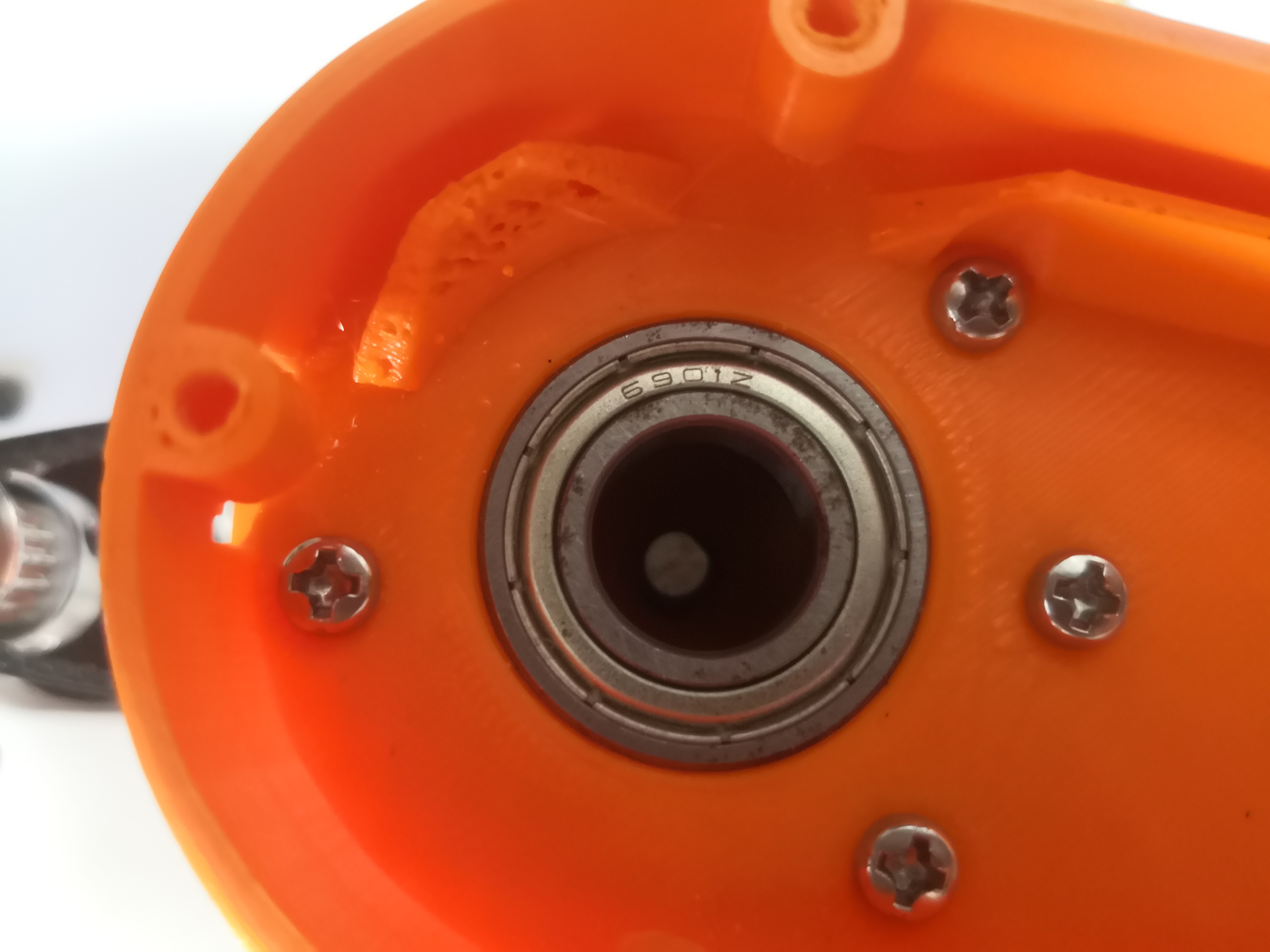
The bearing holder is assembled.
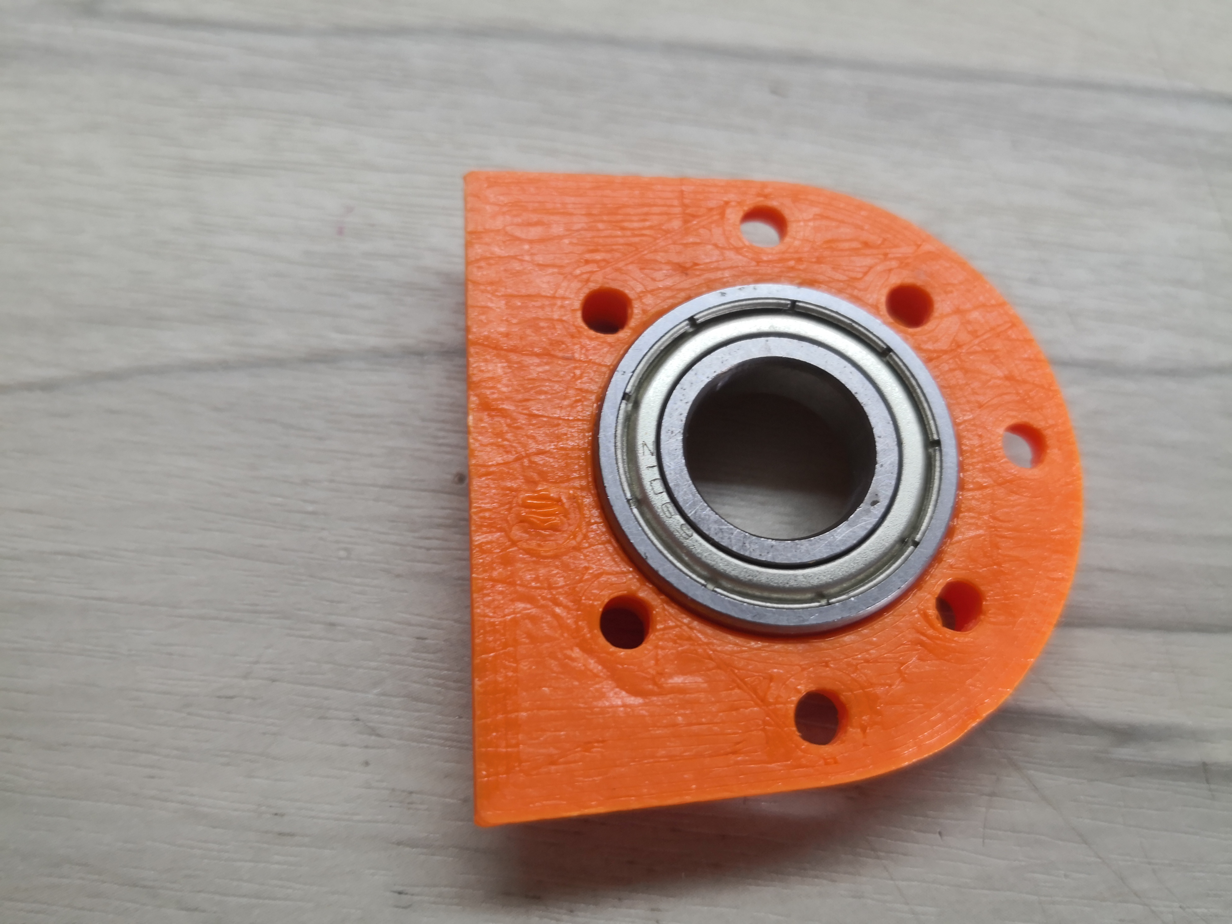
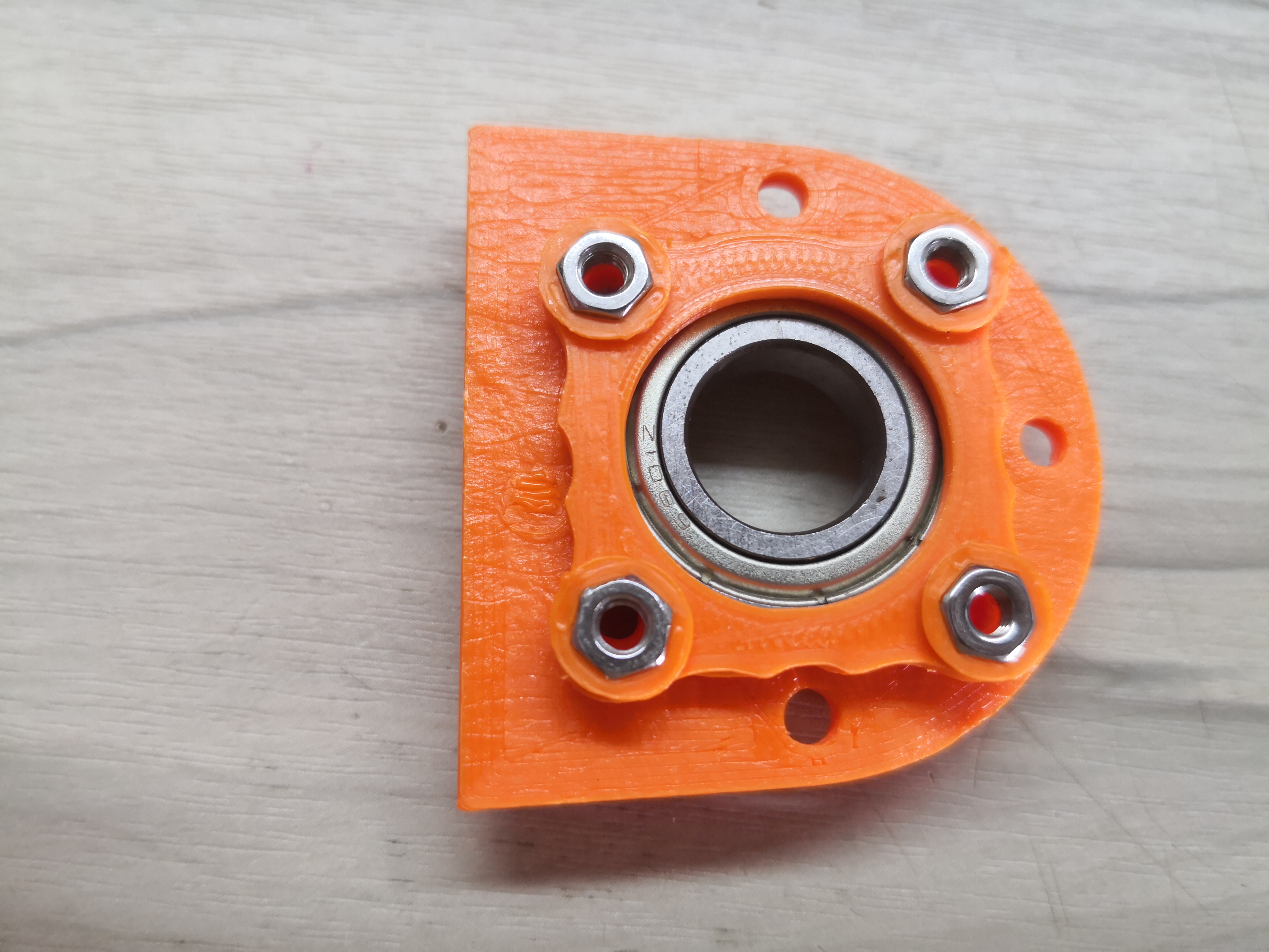
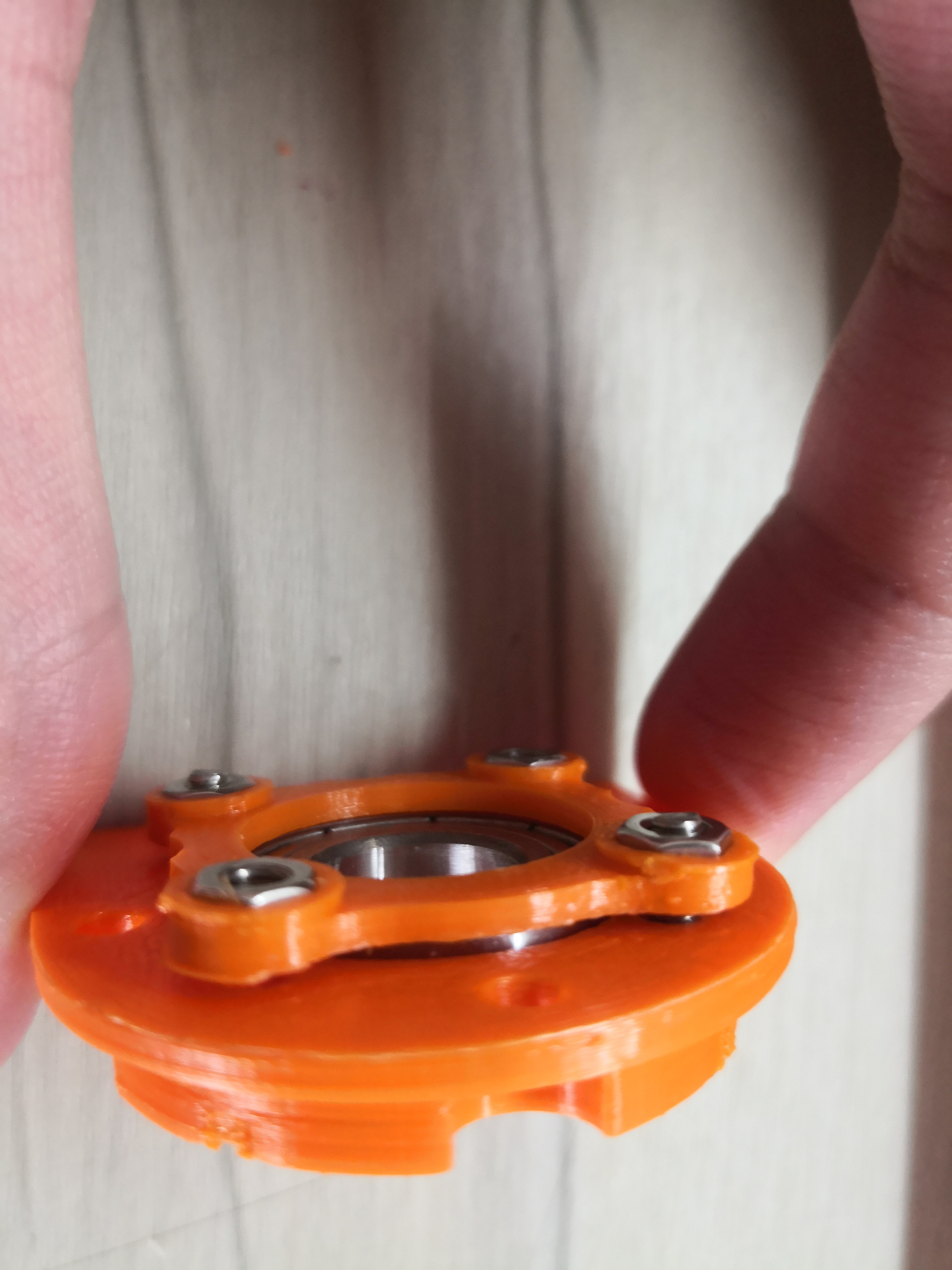
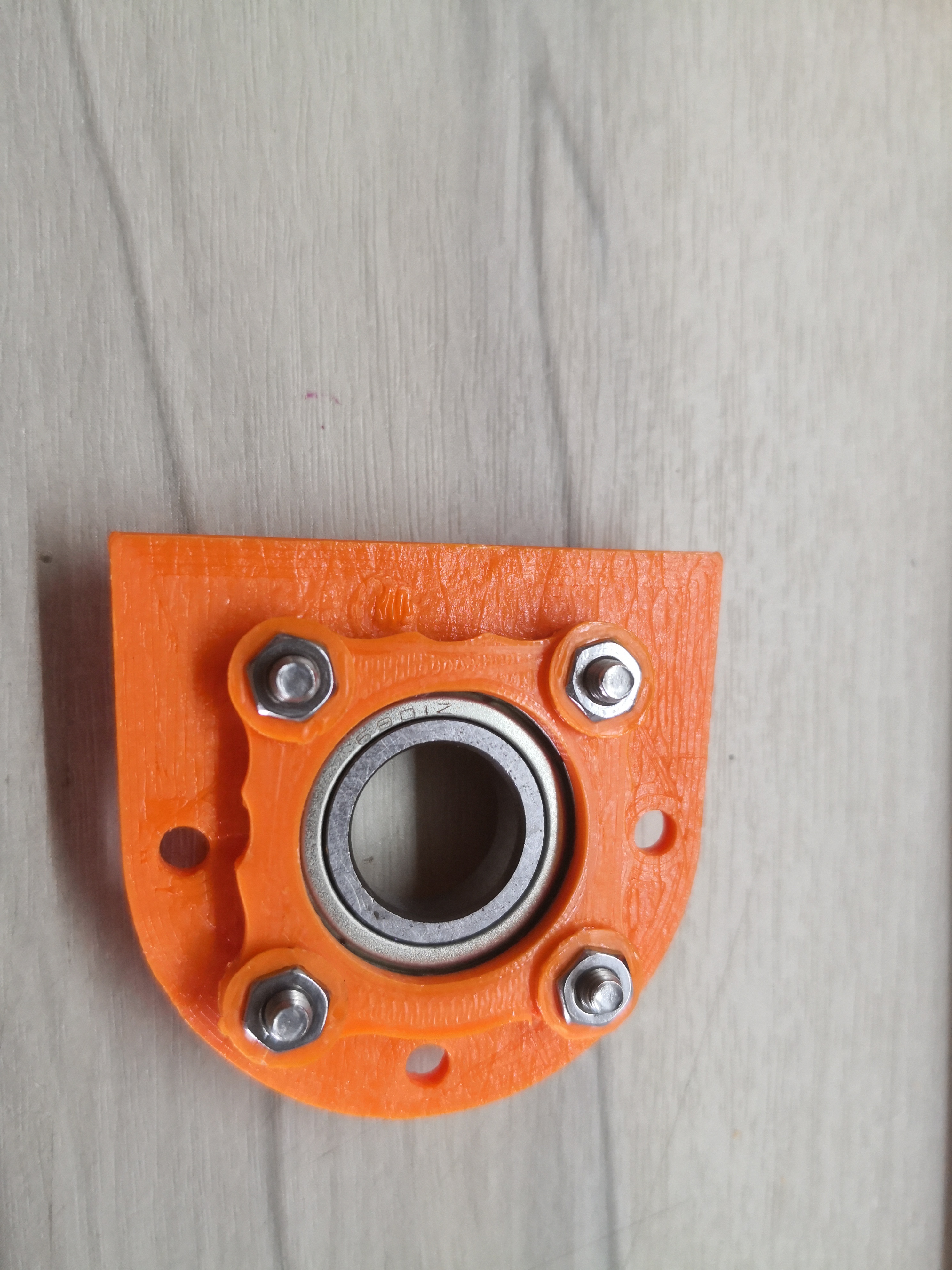
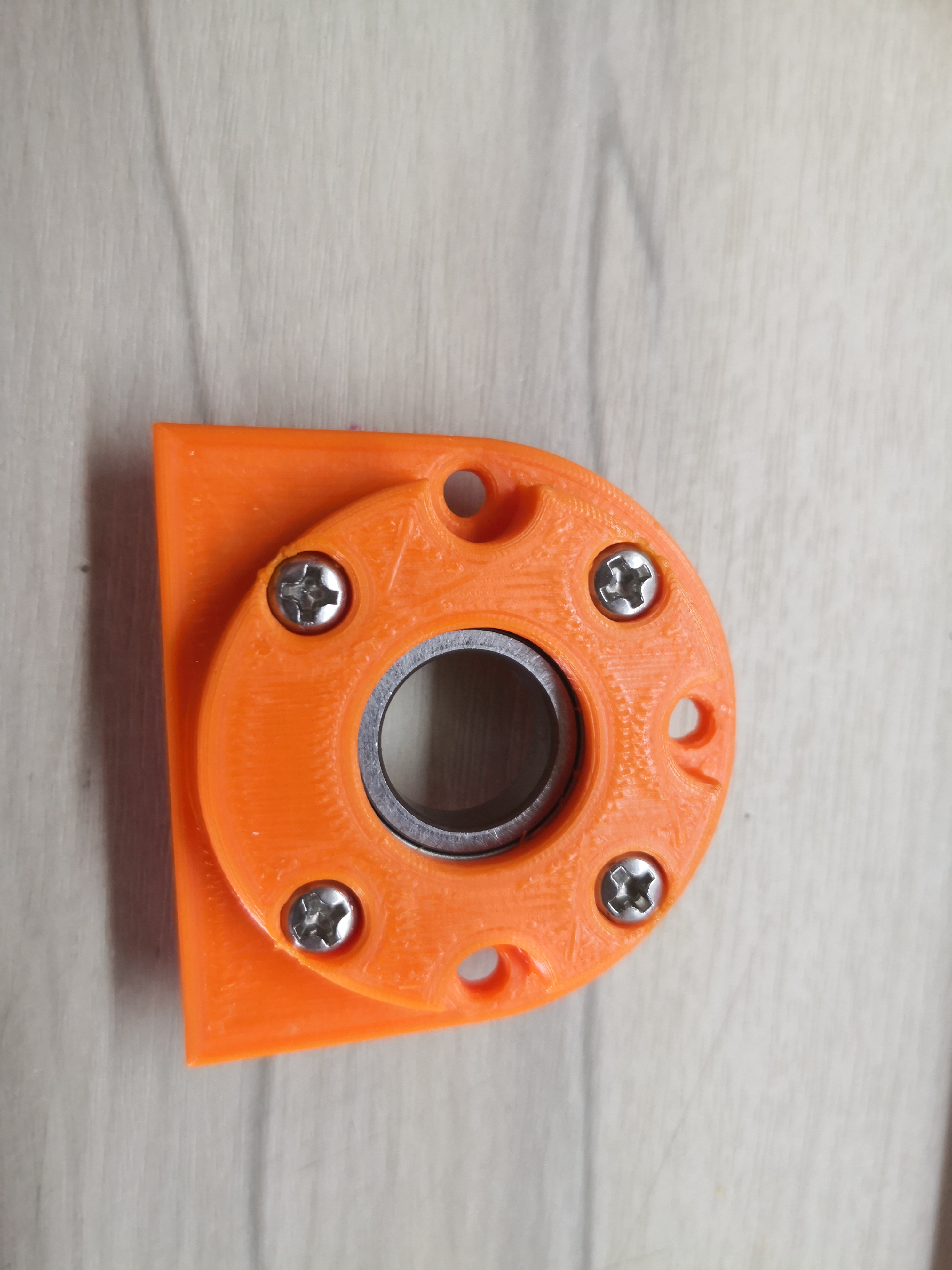
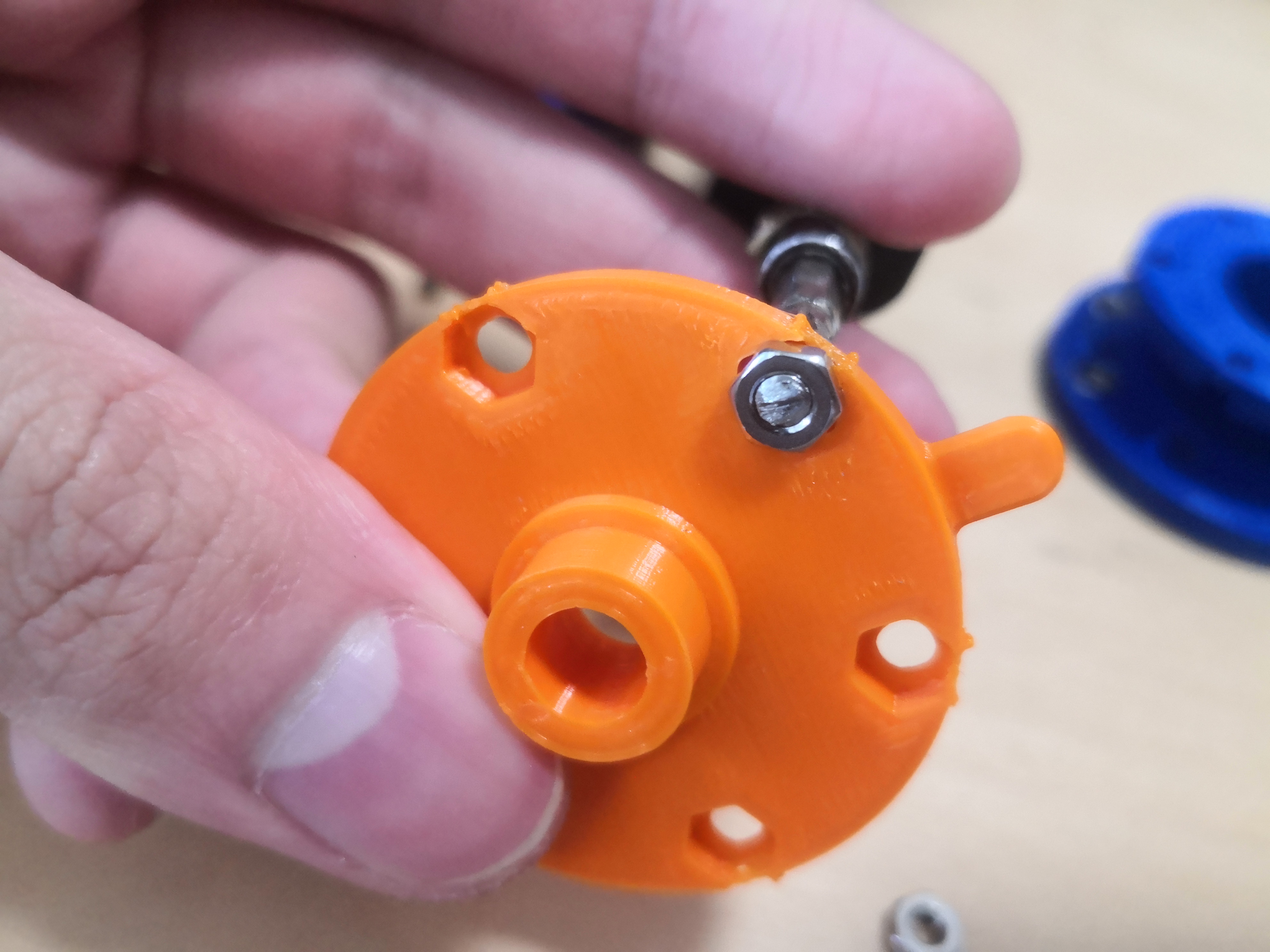
The bearing is pressed into the arm.
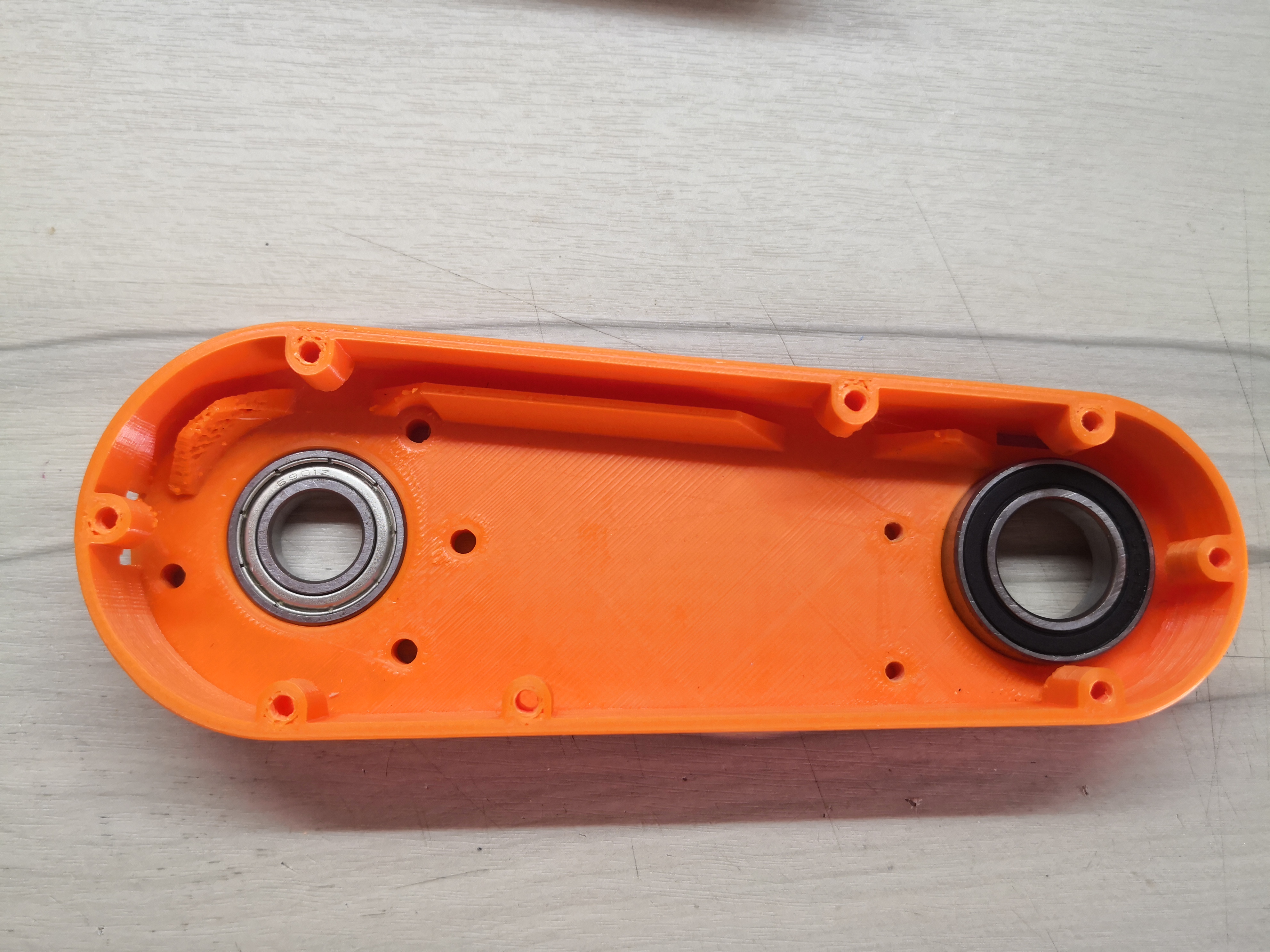
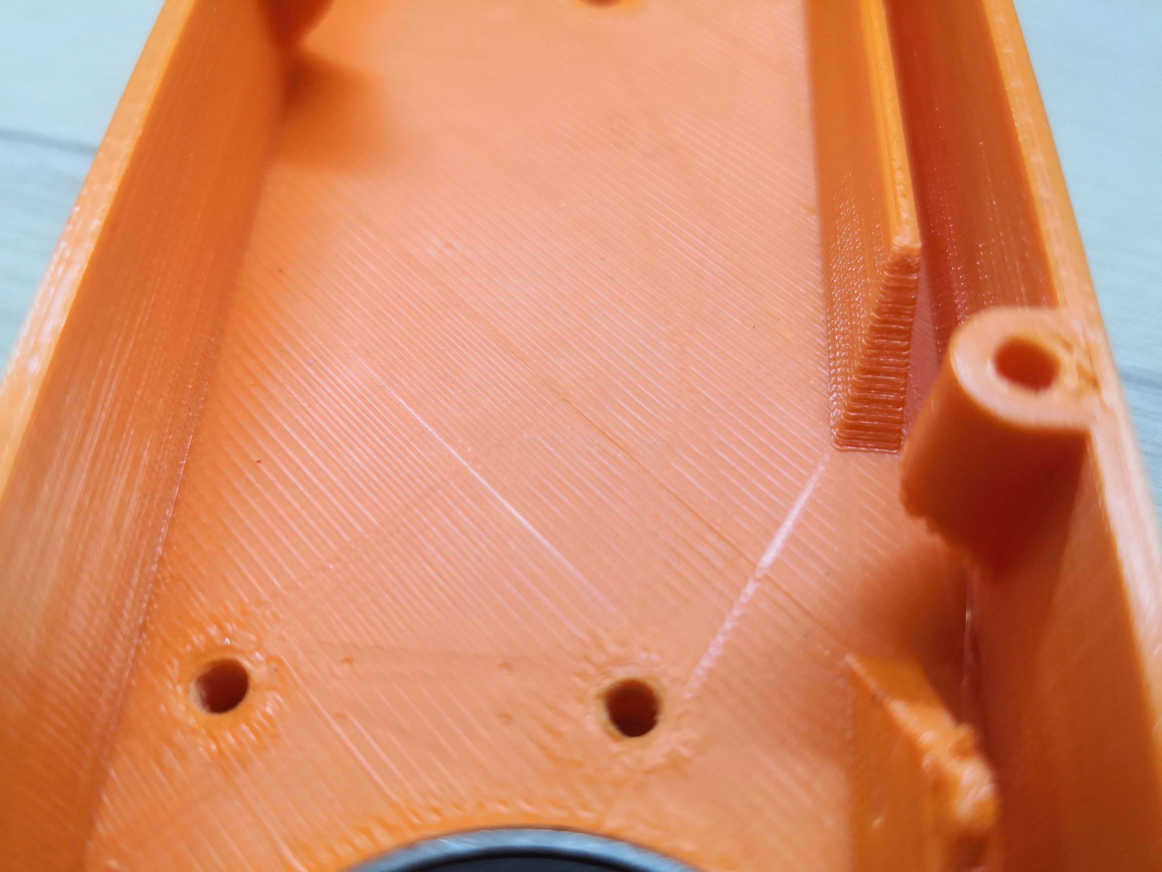
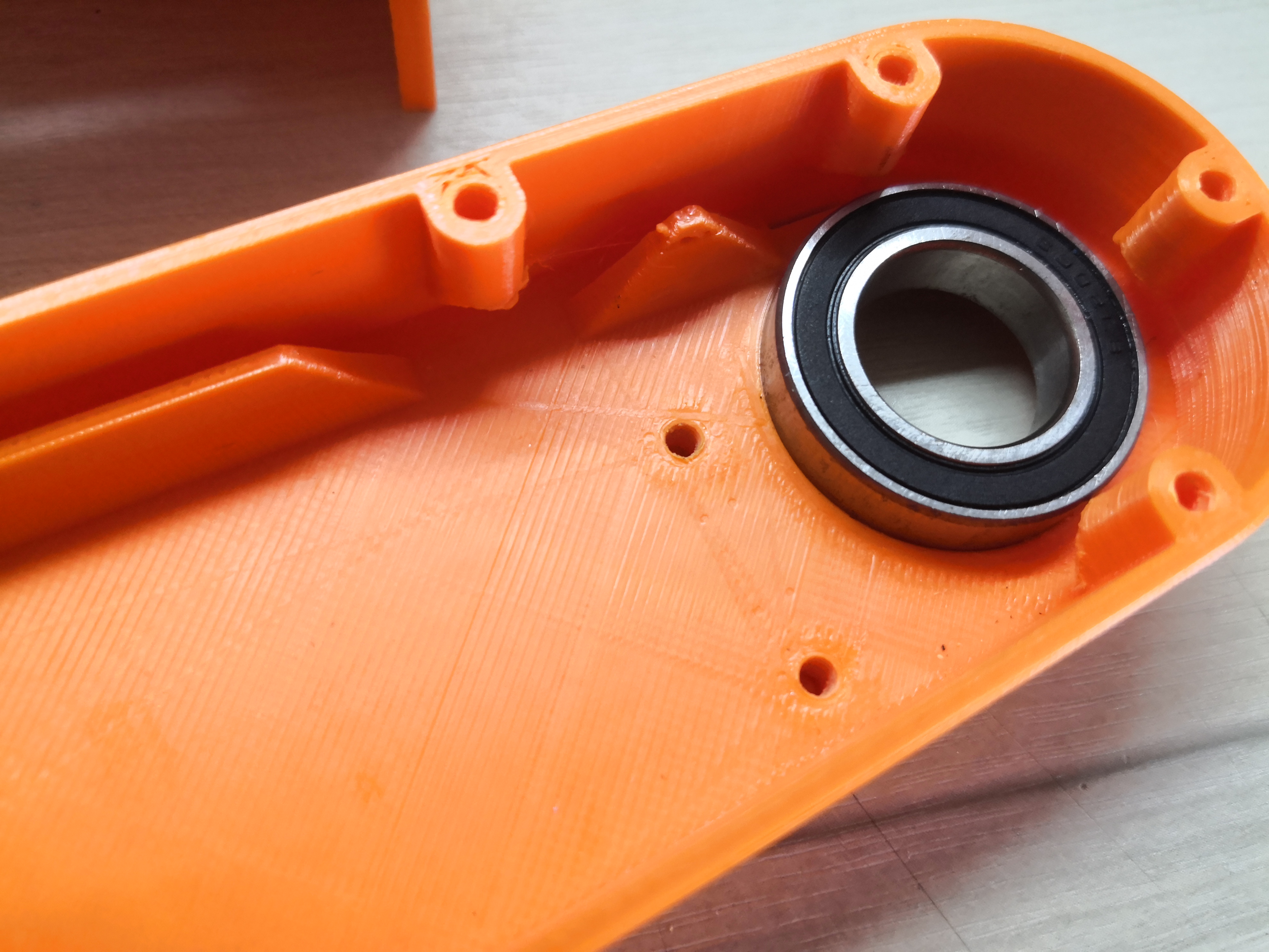
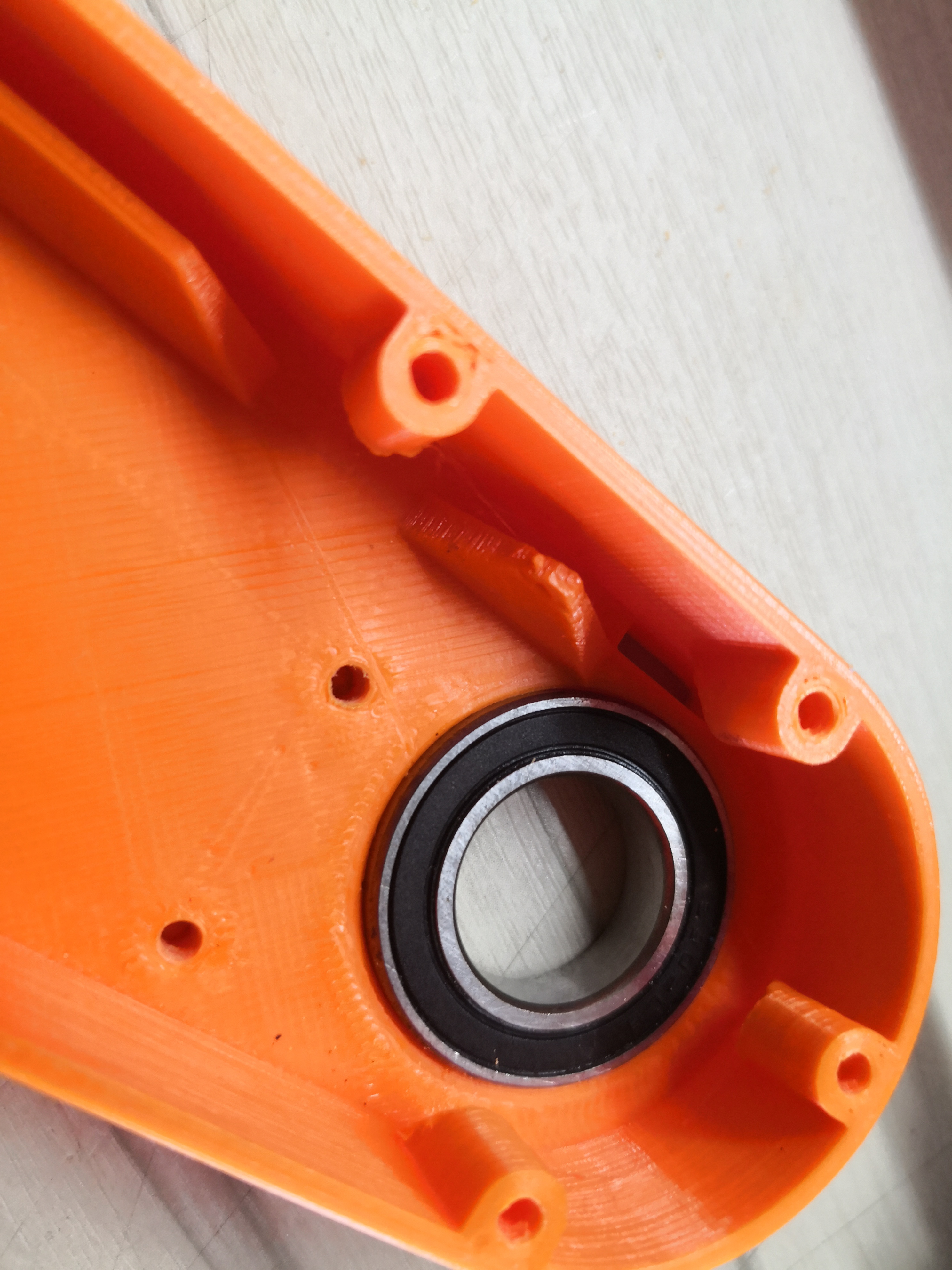
The inner arm is done.
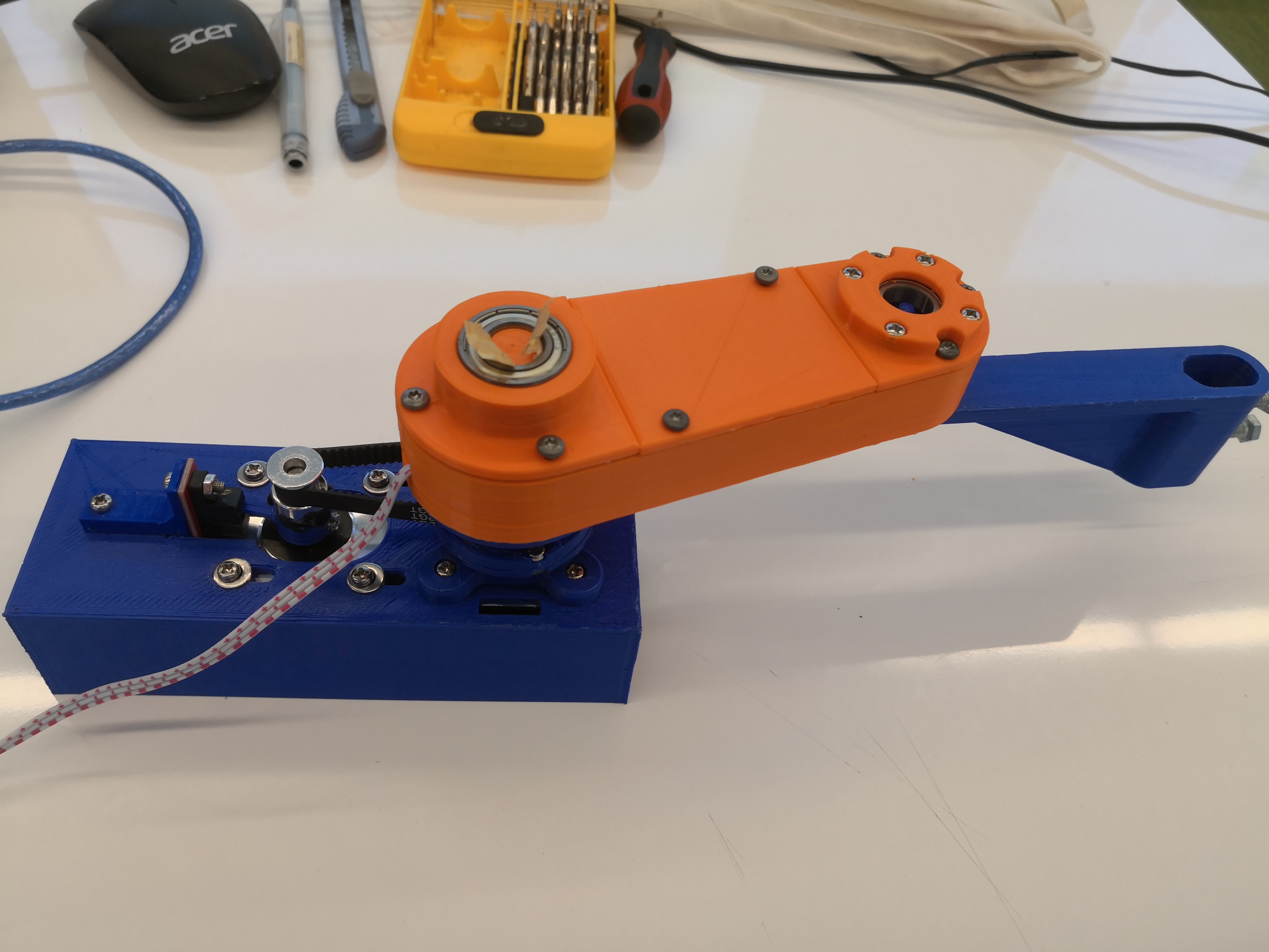
The new test base is printed. Tha arm is mounted to the new base.
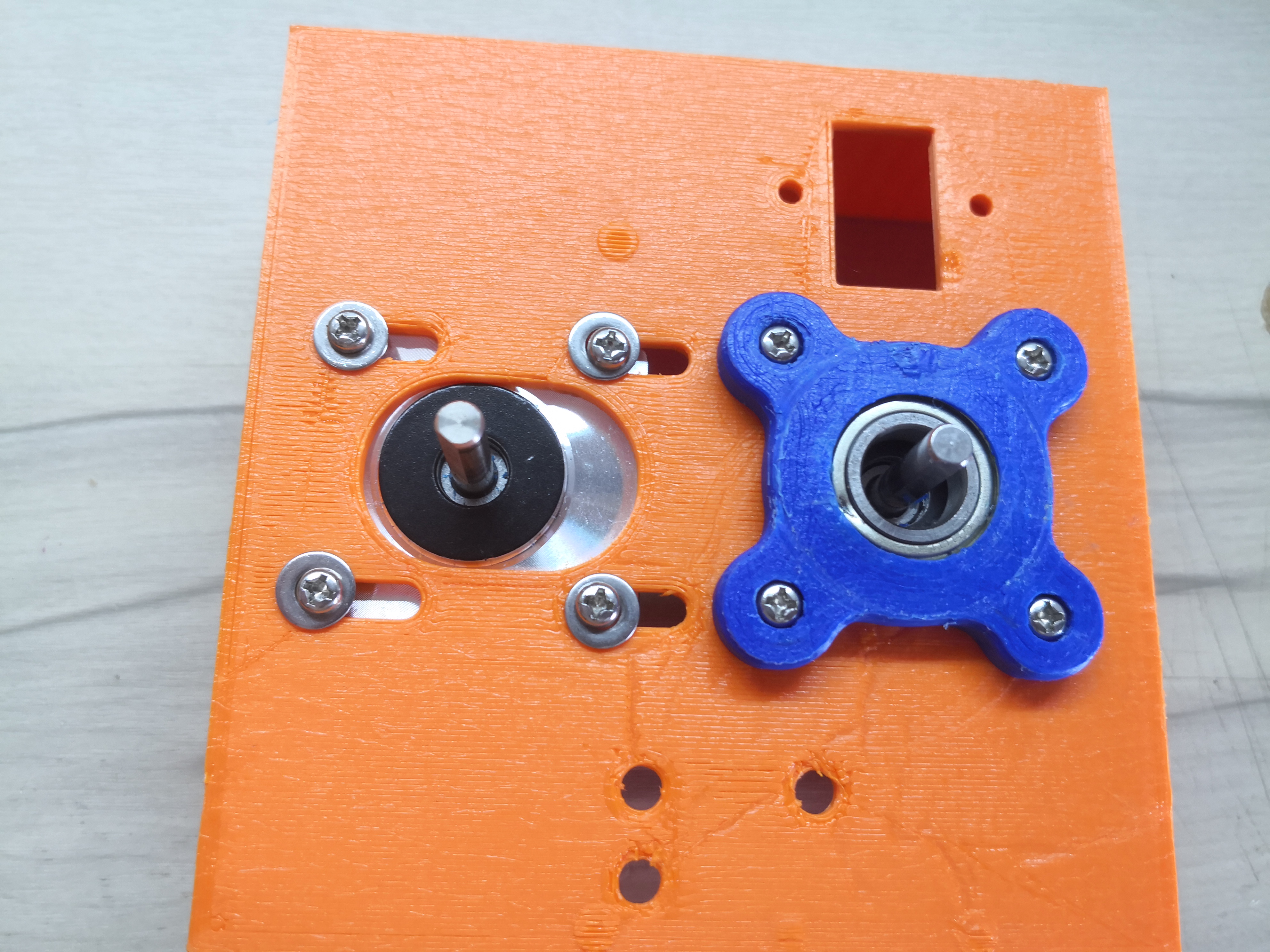
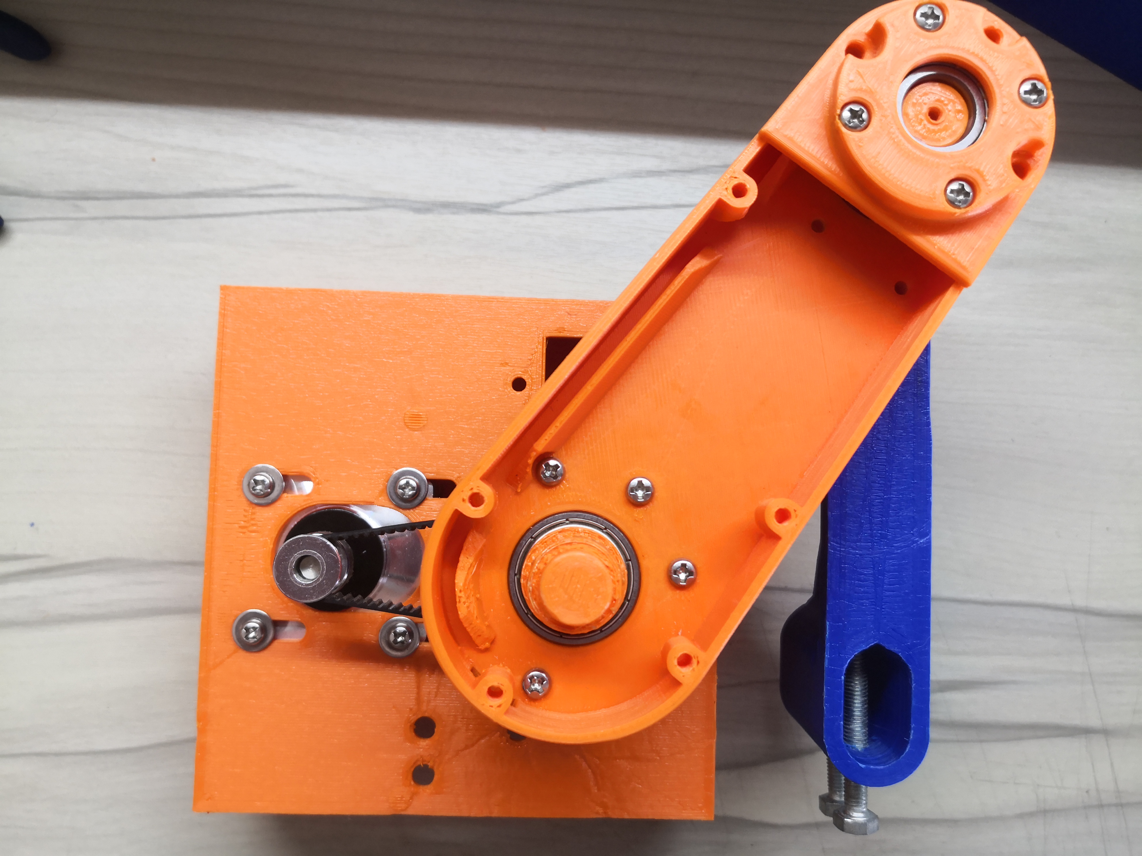
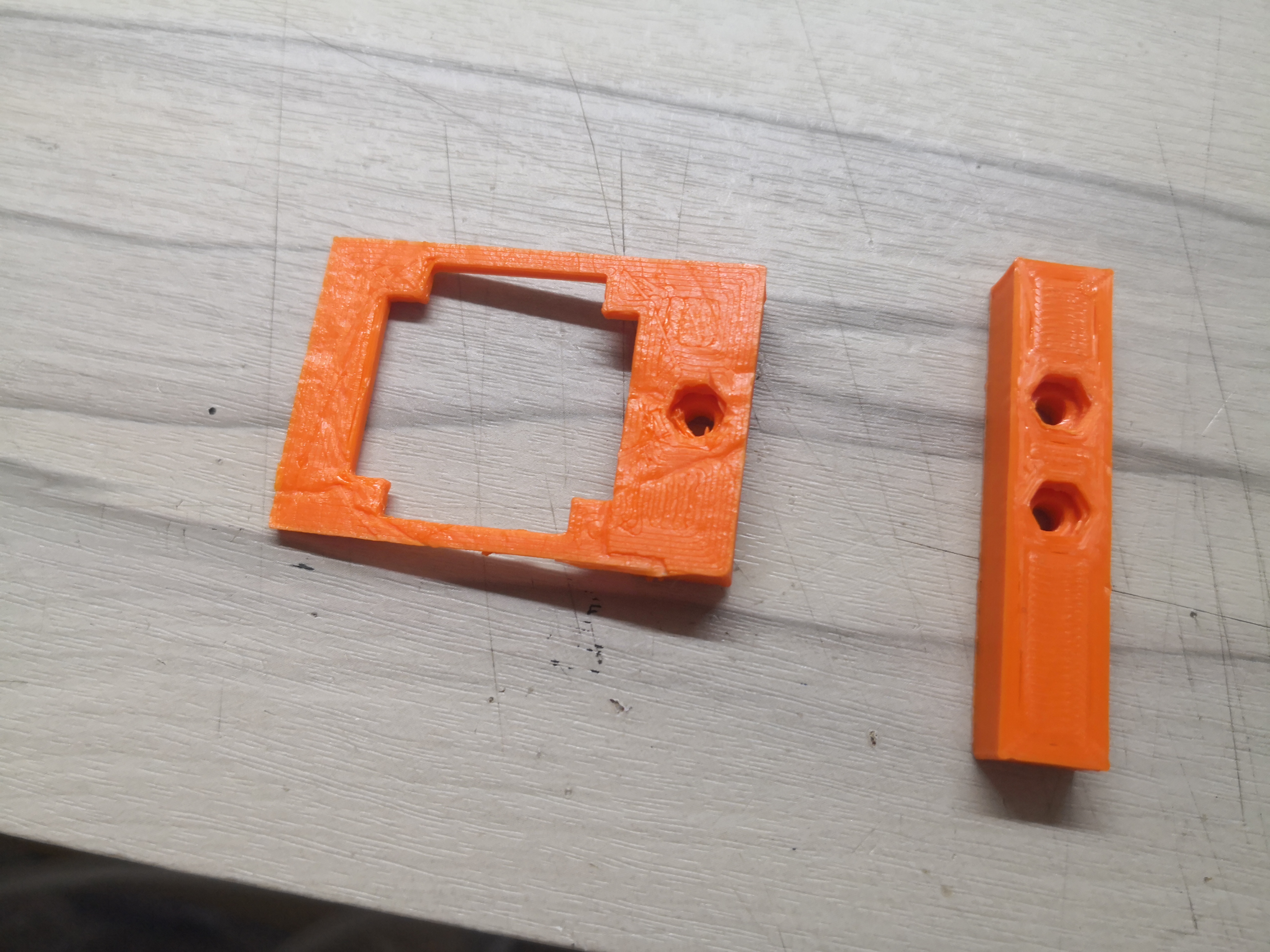
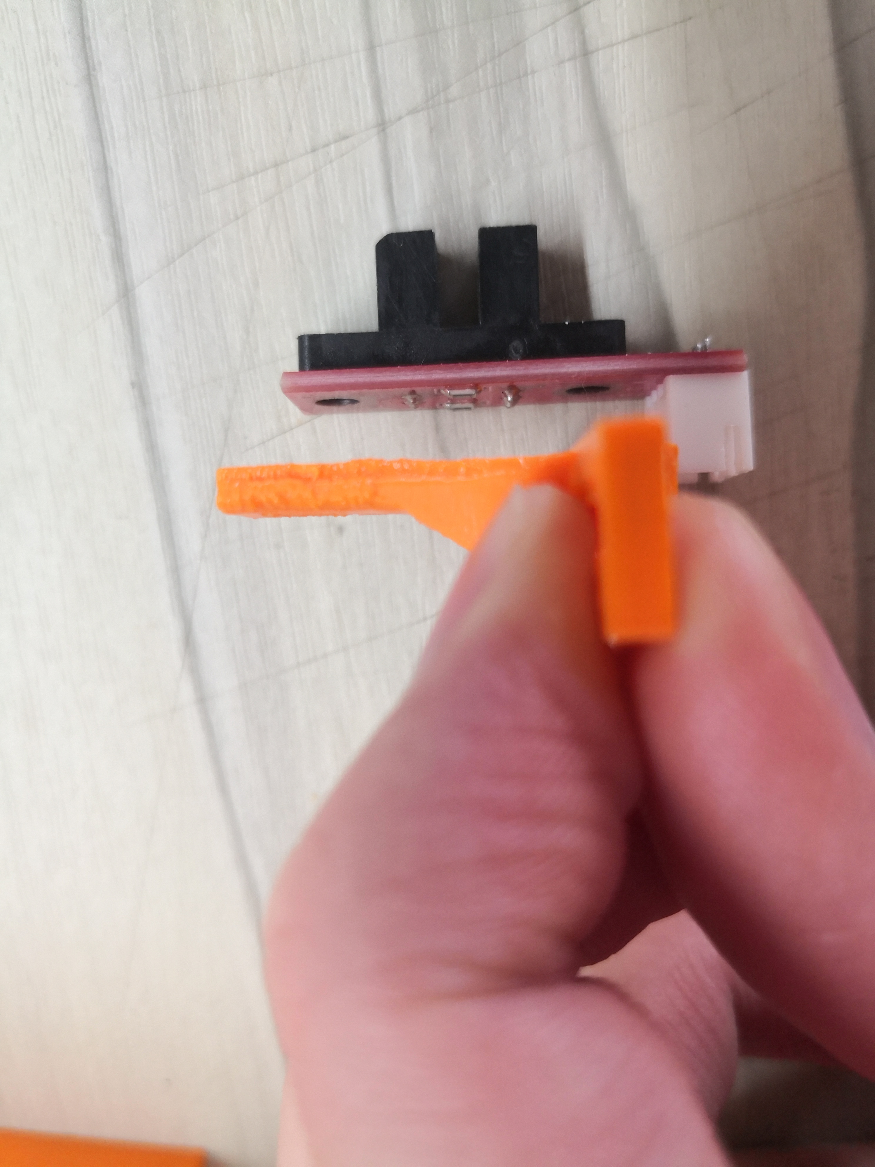
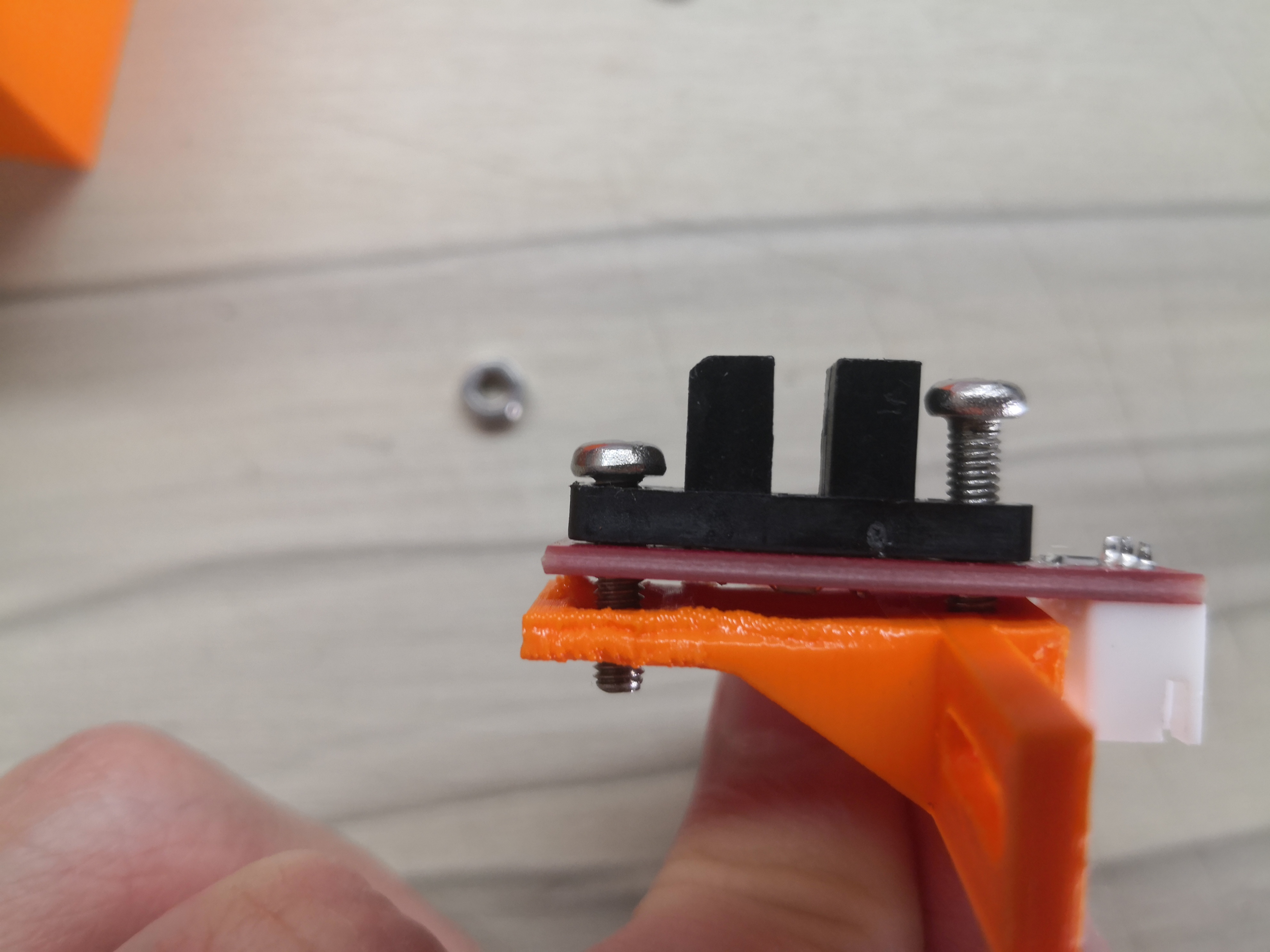
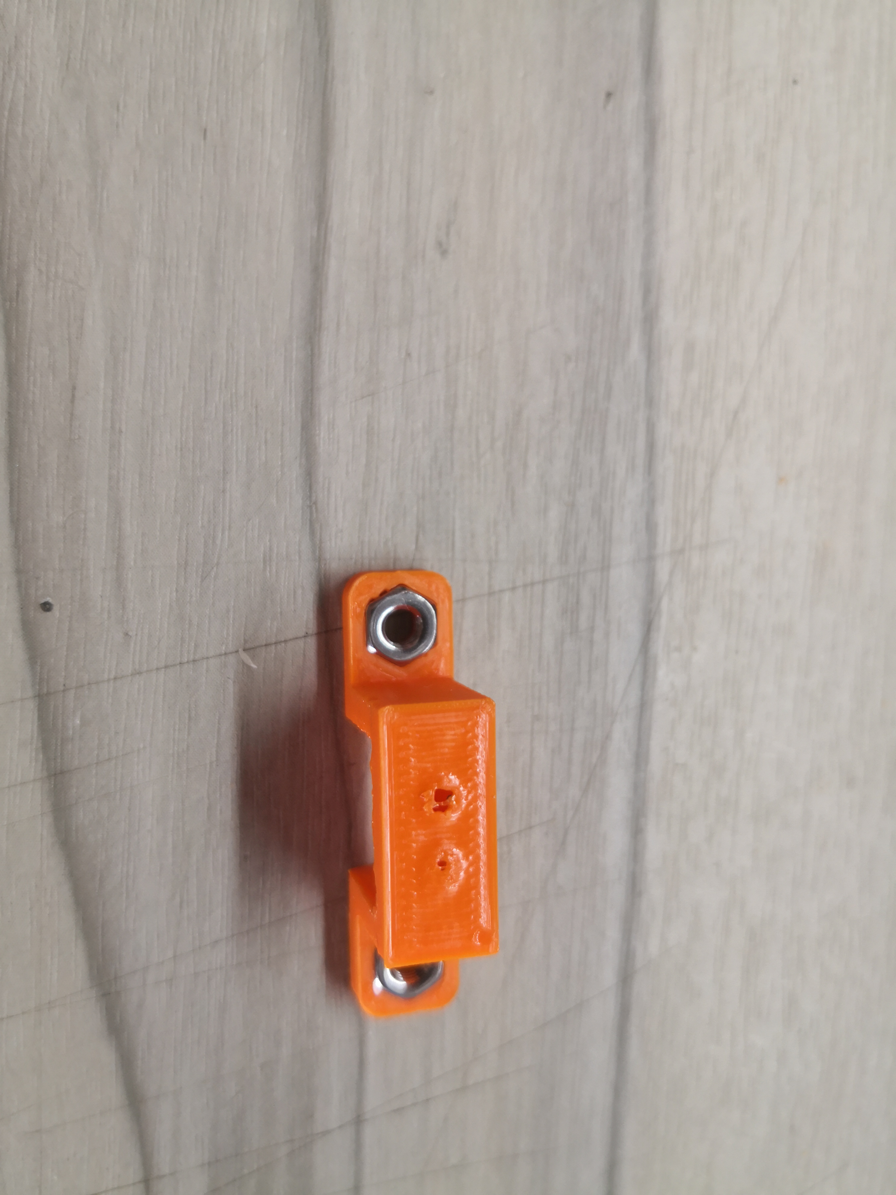
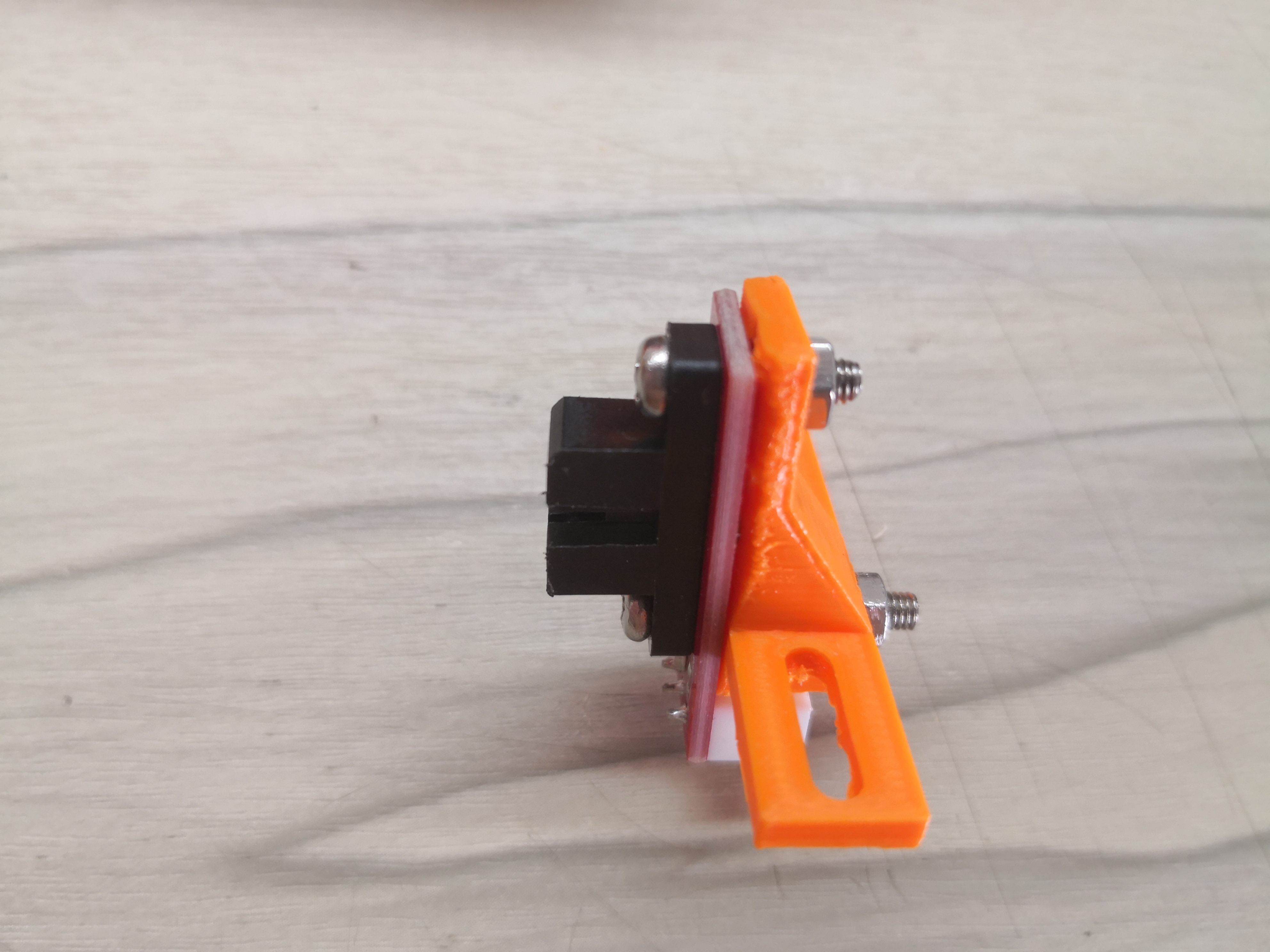
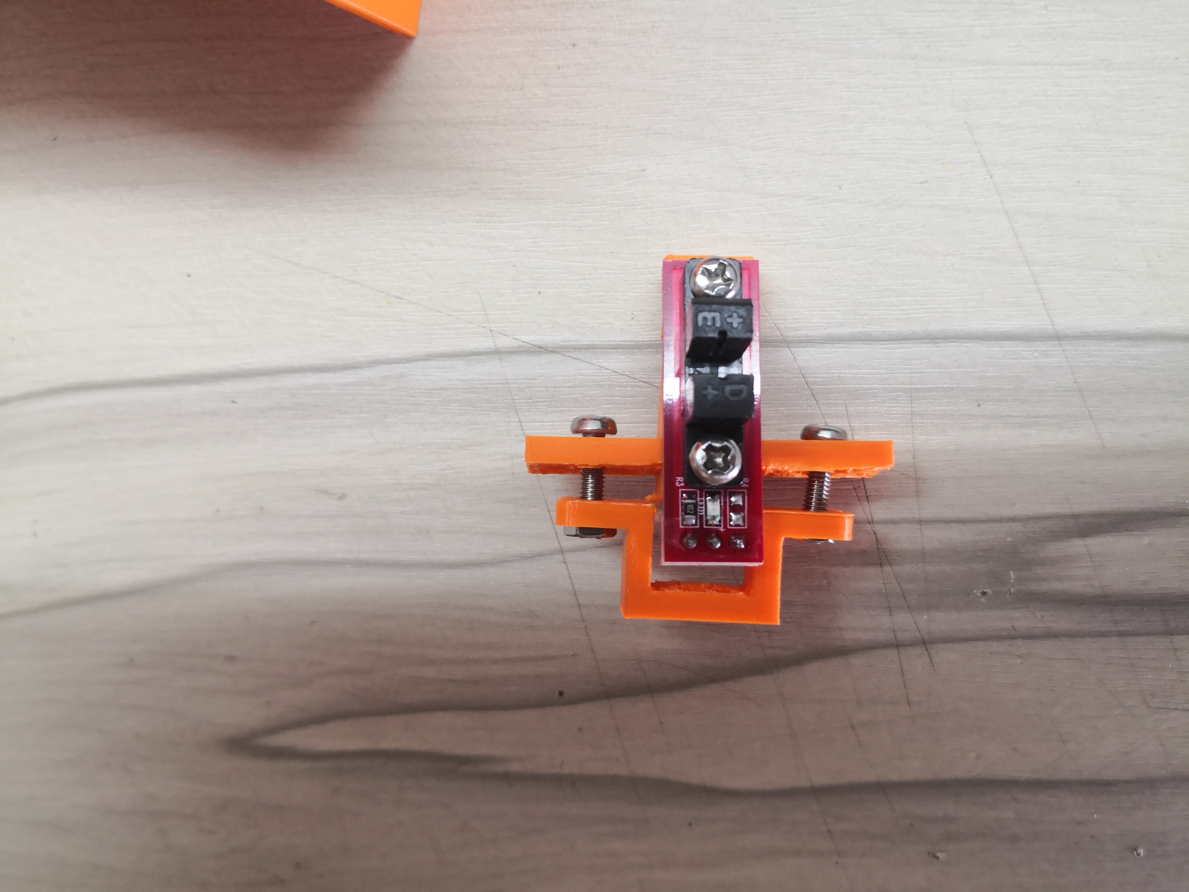
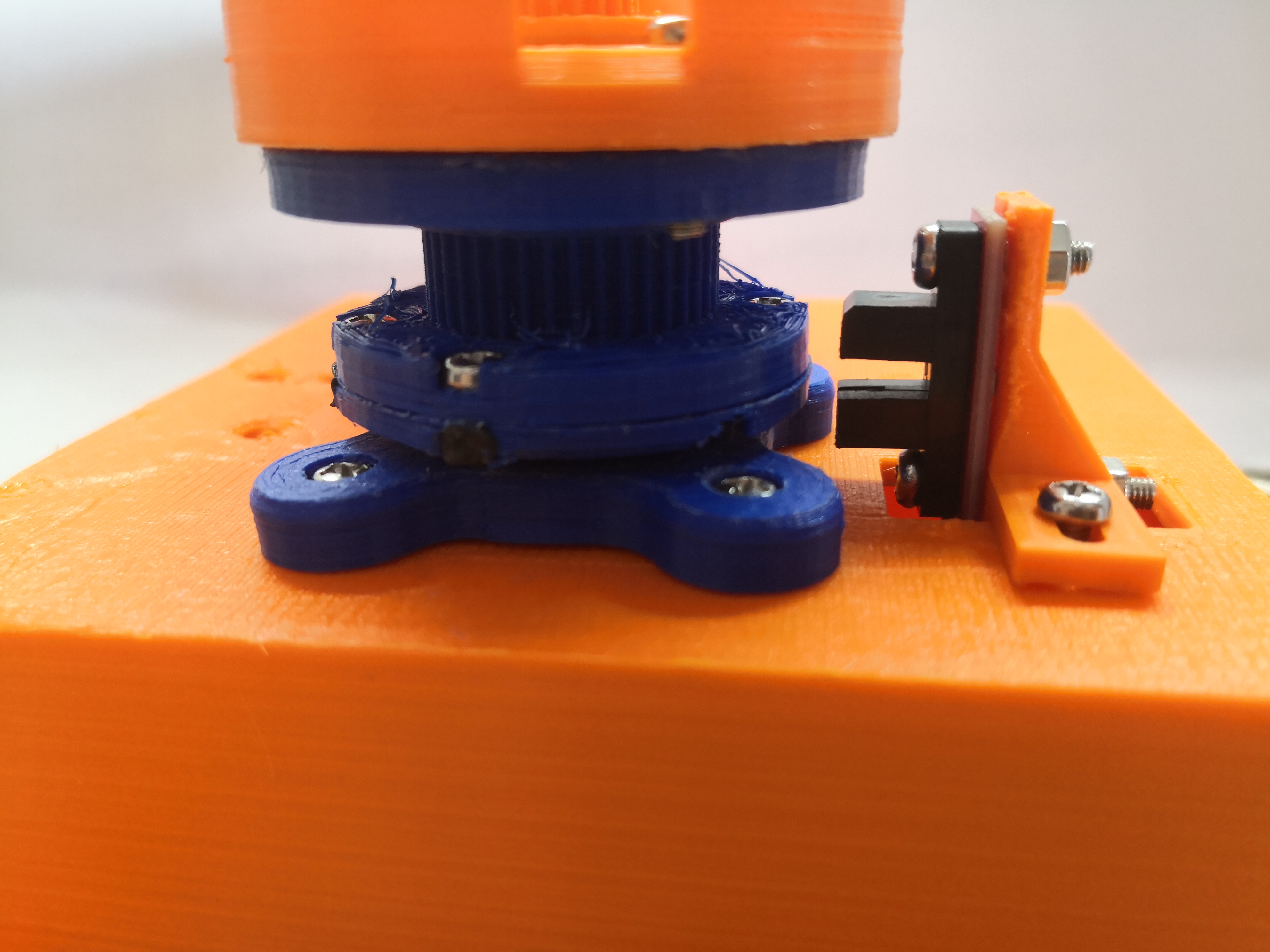
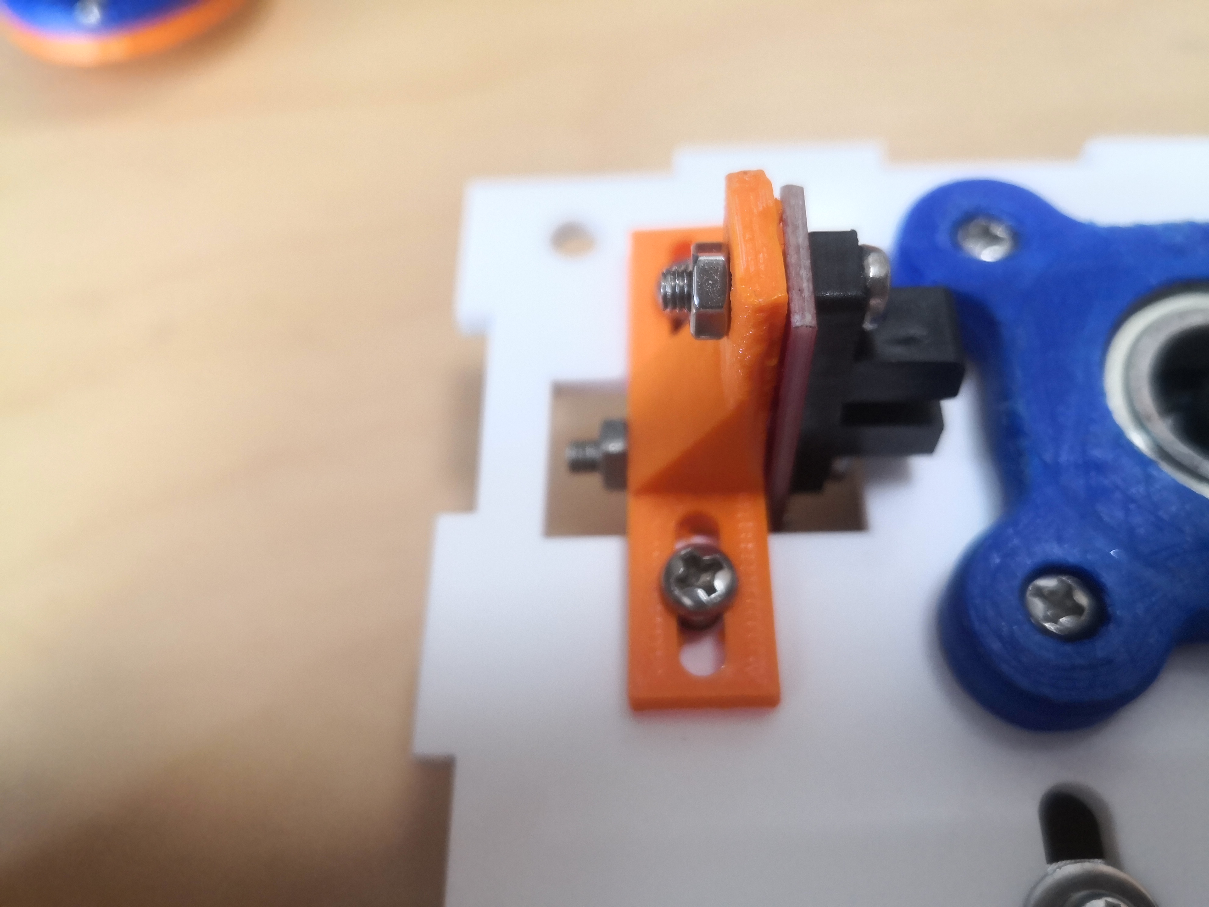
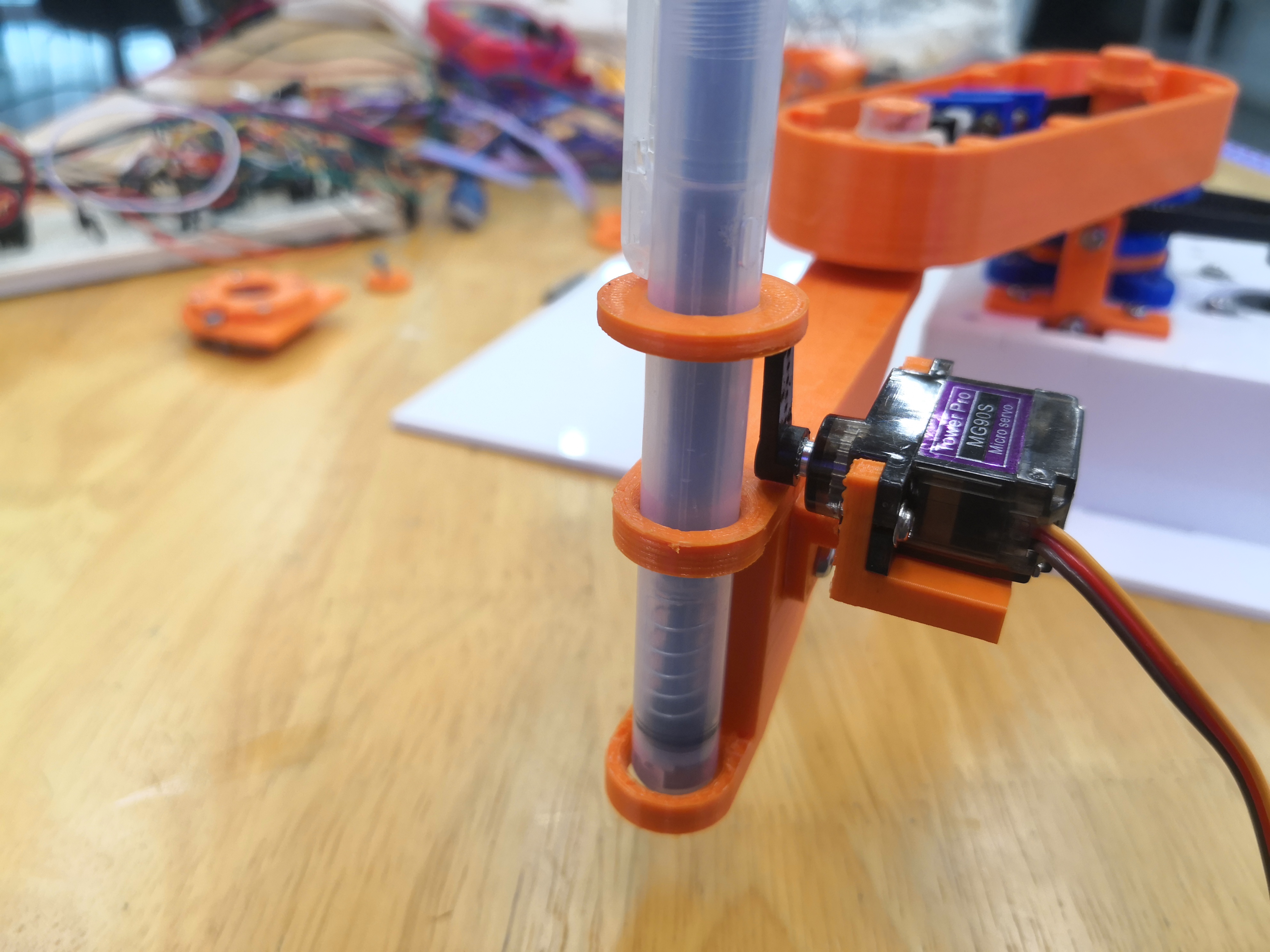
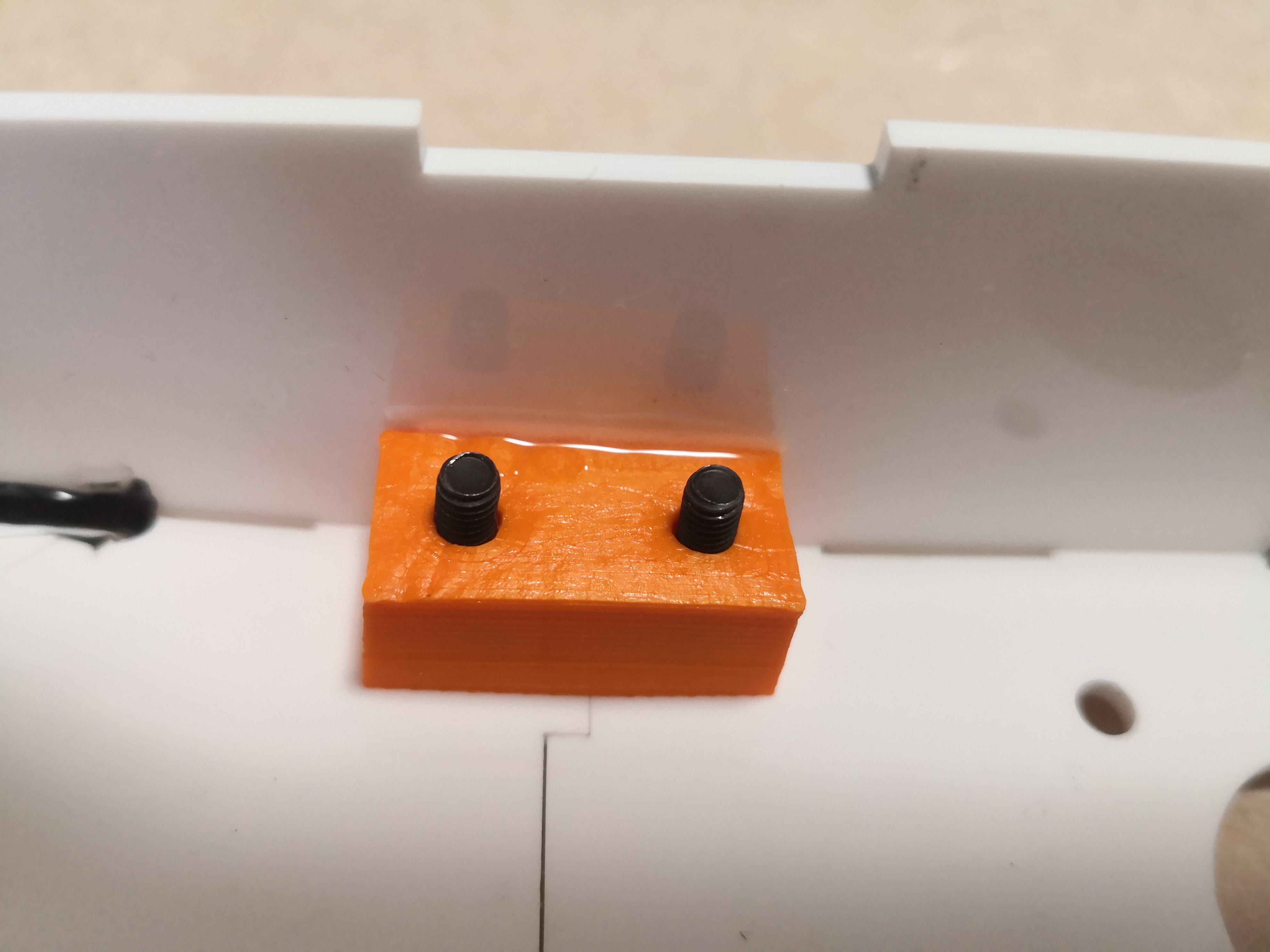
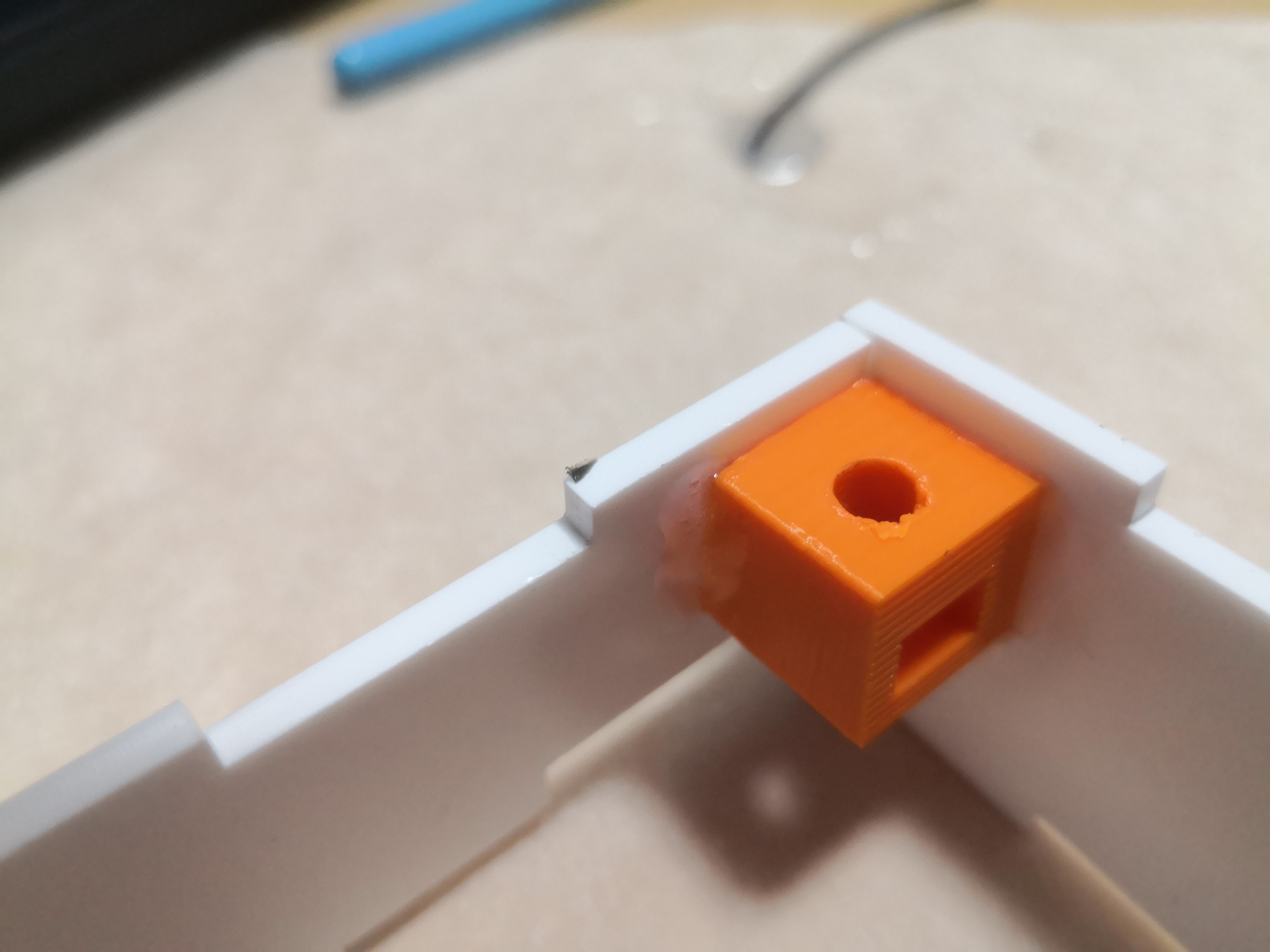
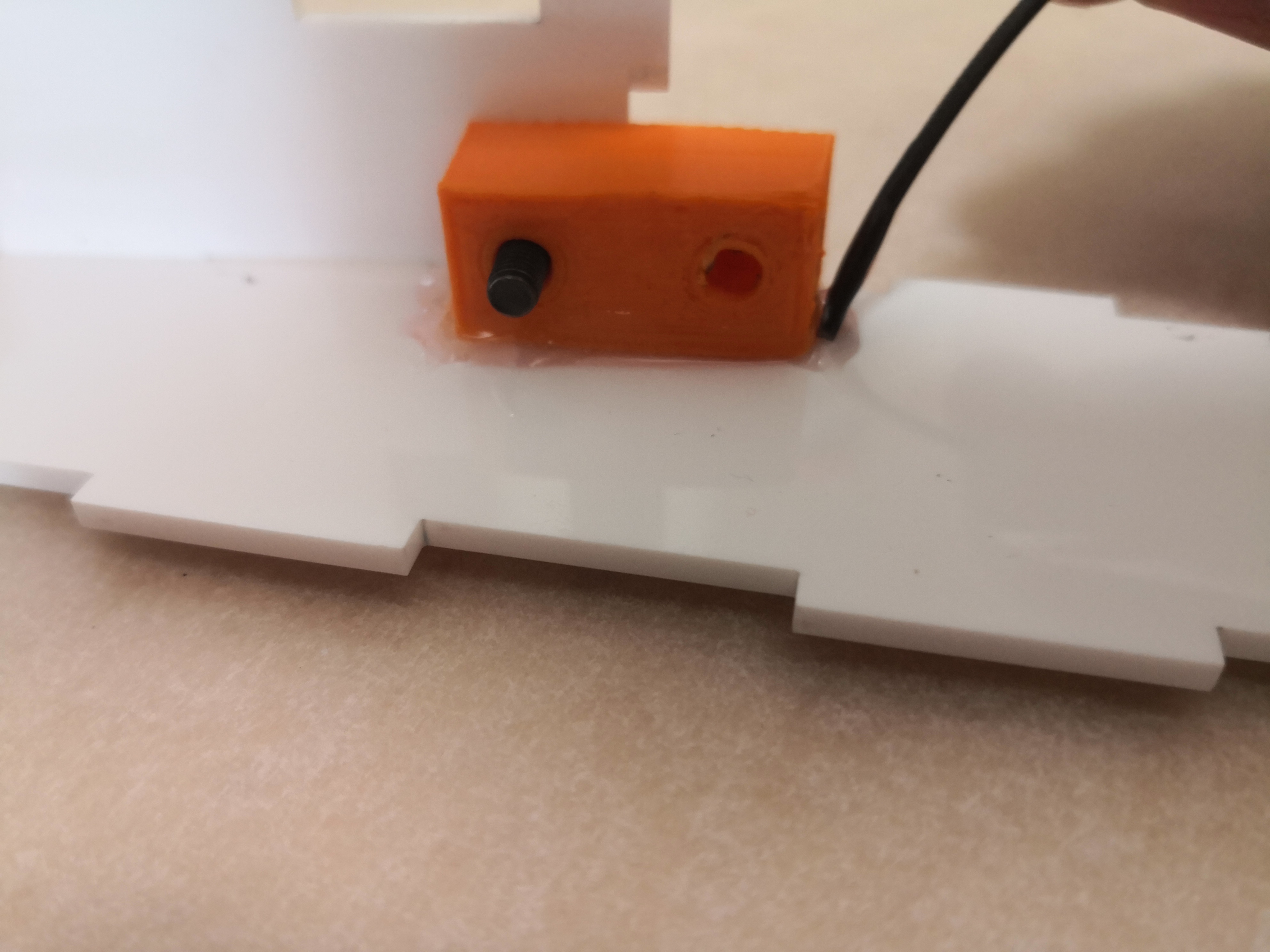
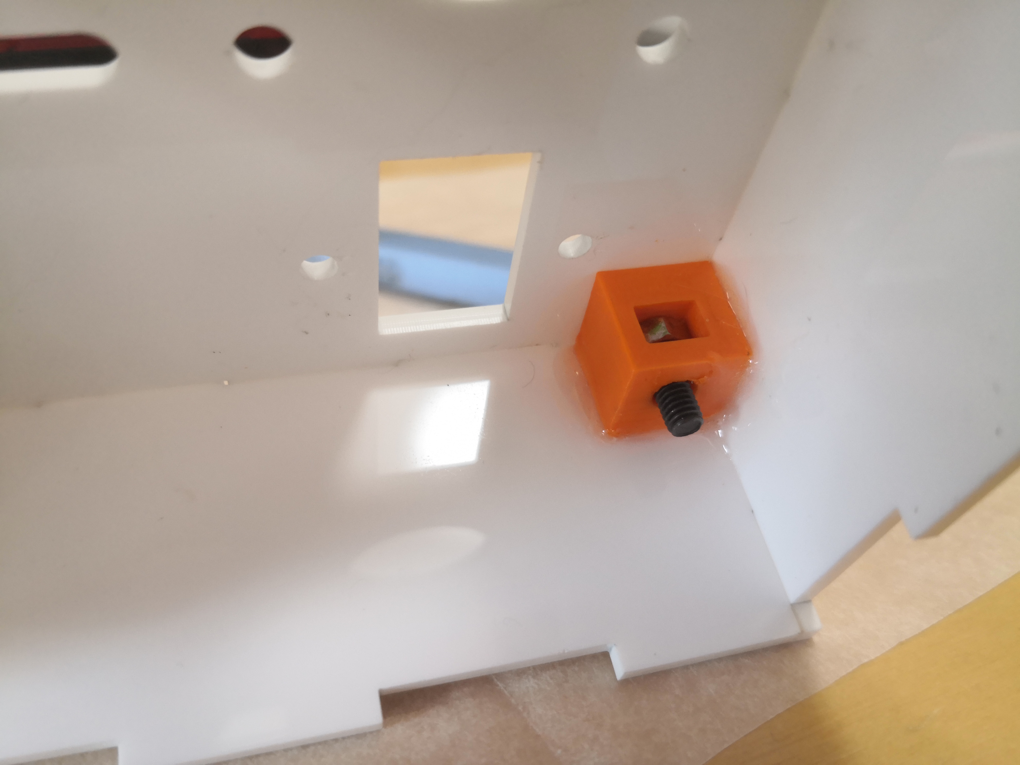
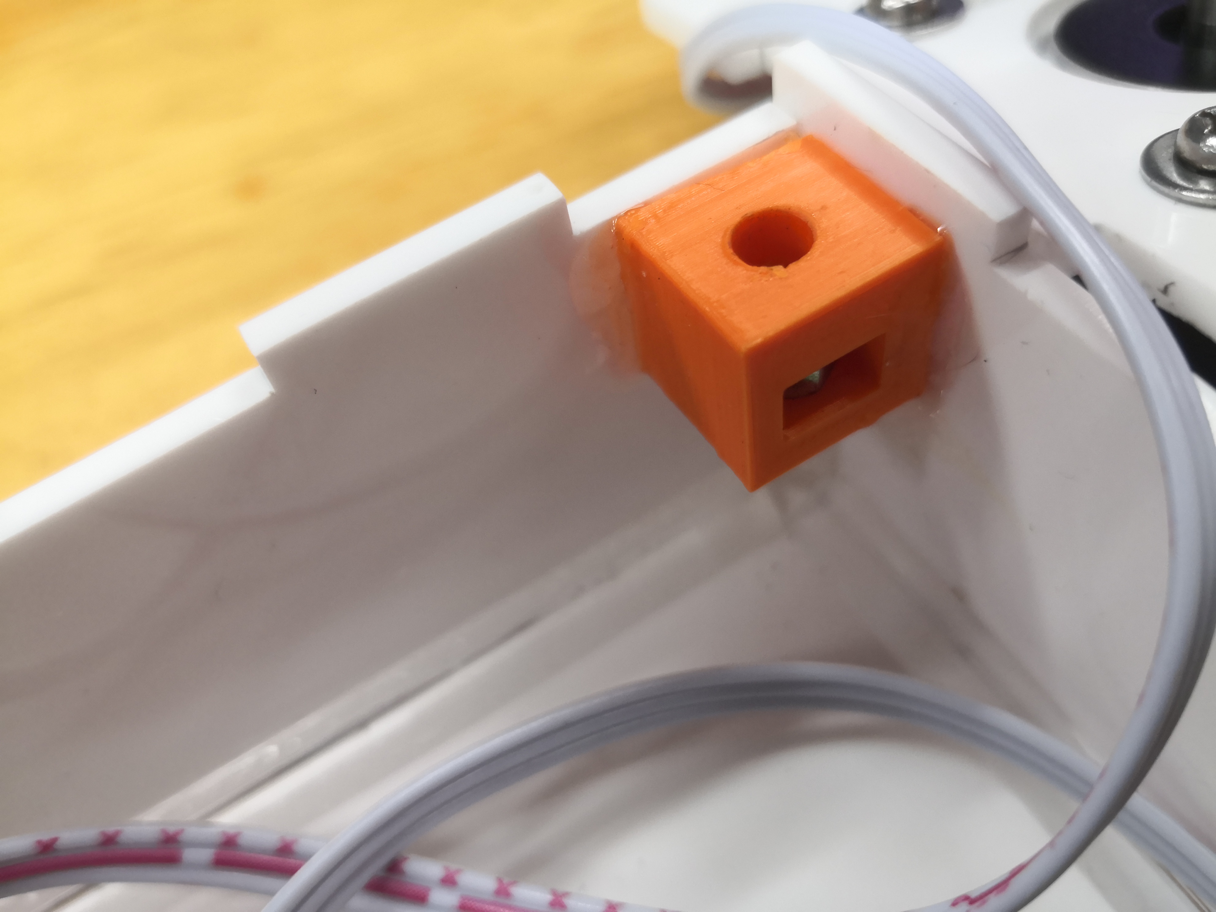
The new limit switch holder is printed, assembled and fixed to the base.
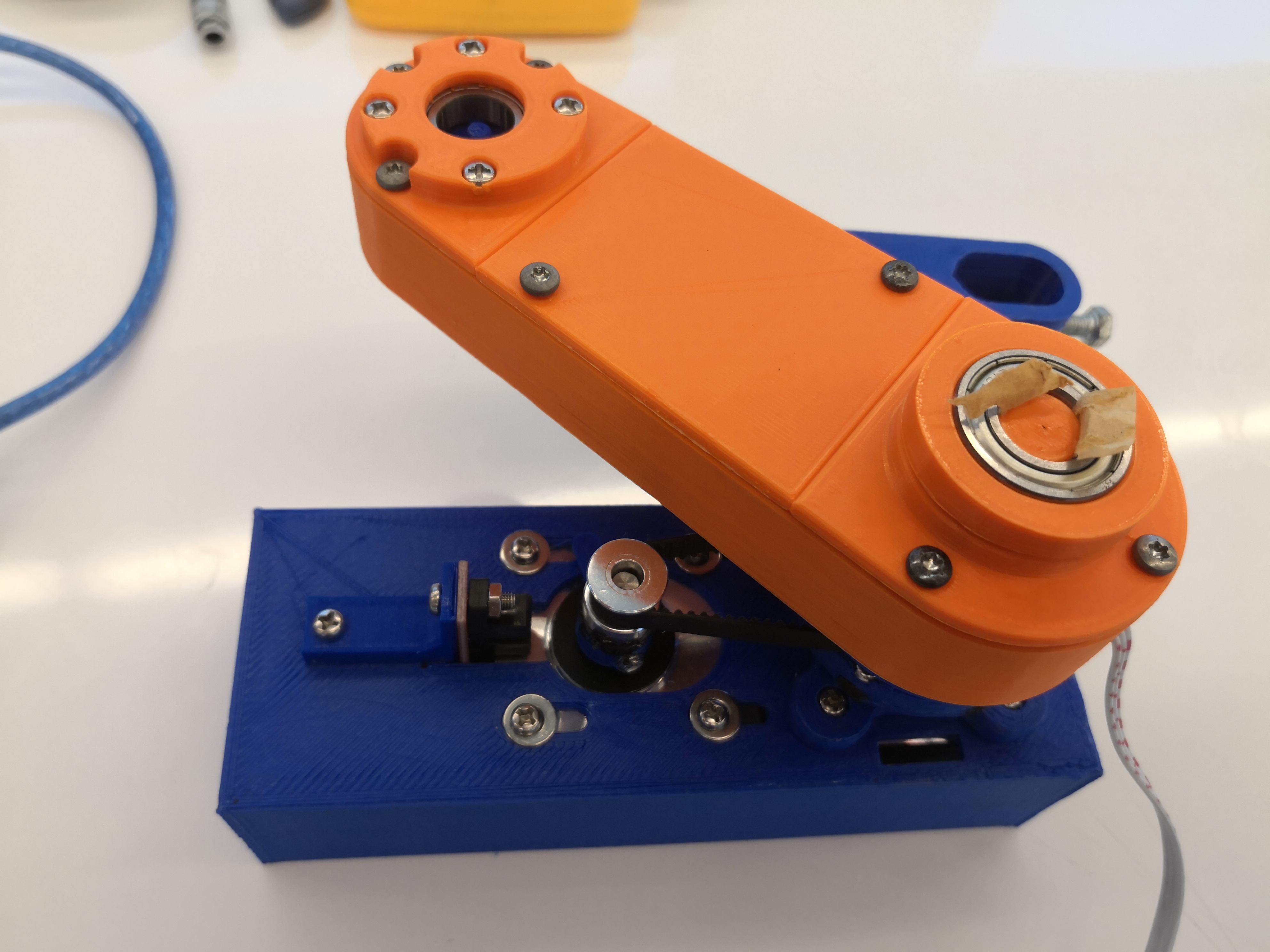
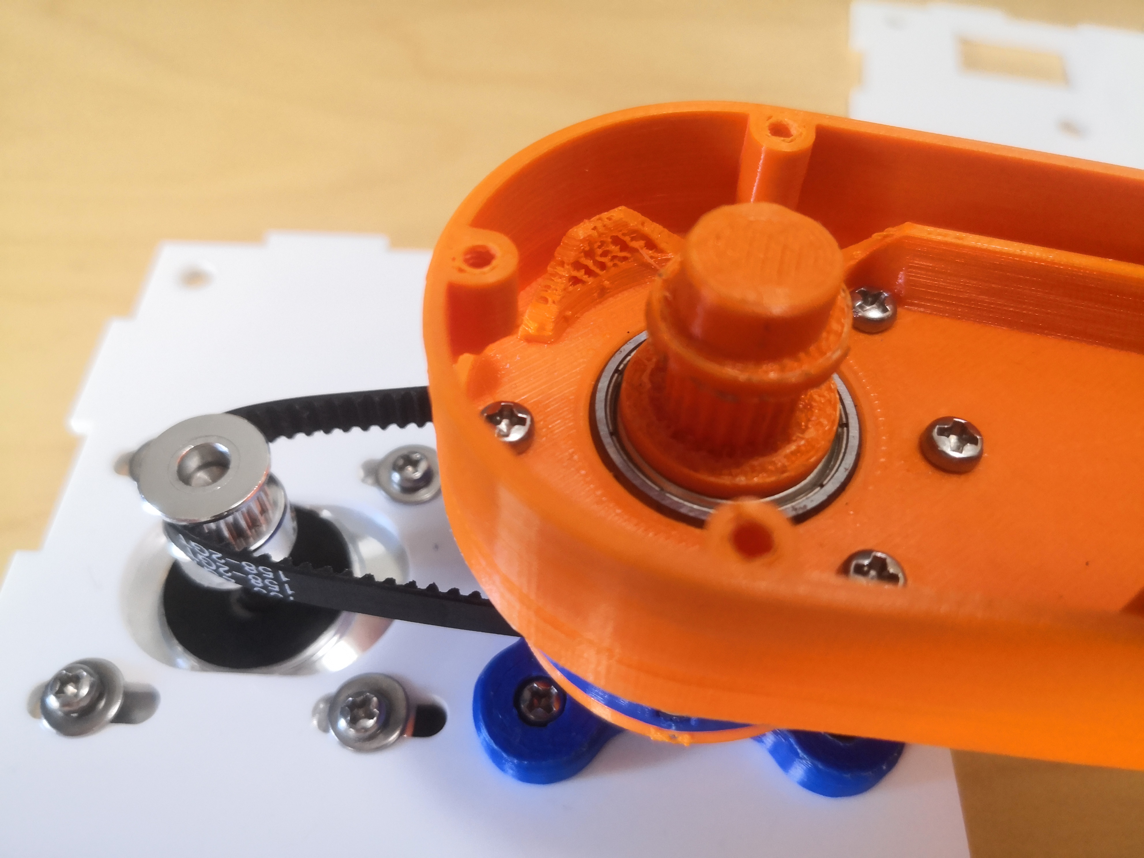
The new pulley is assembled.
The pen plotter is assembled.
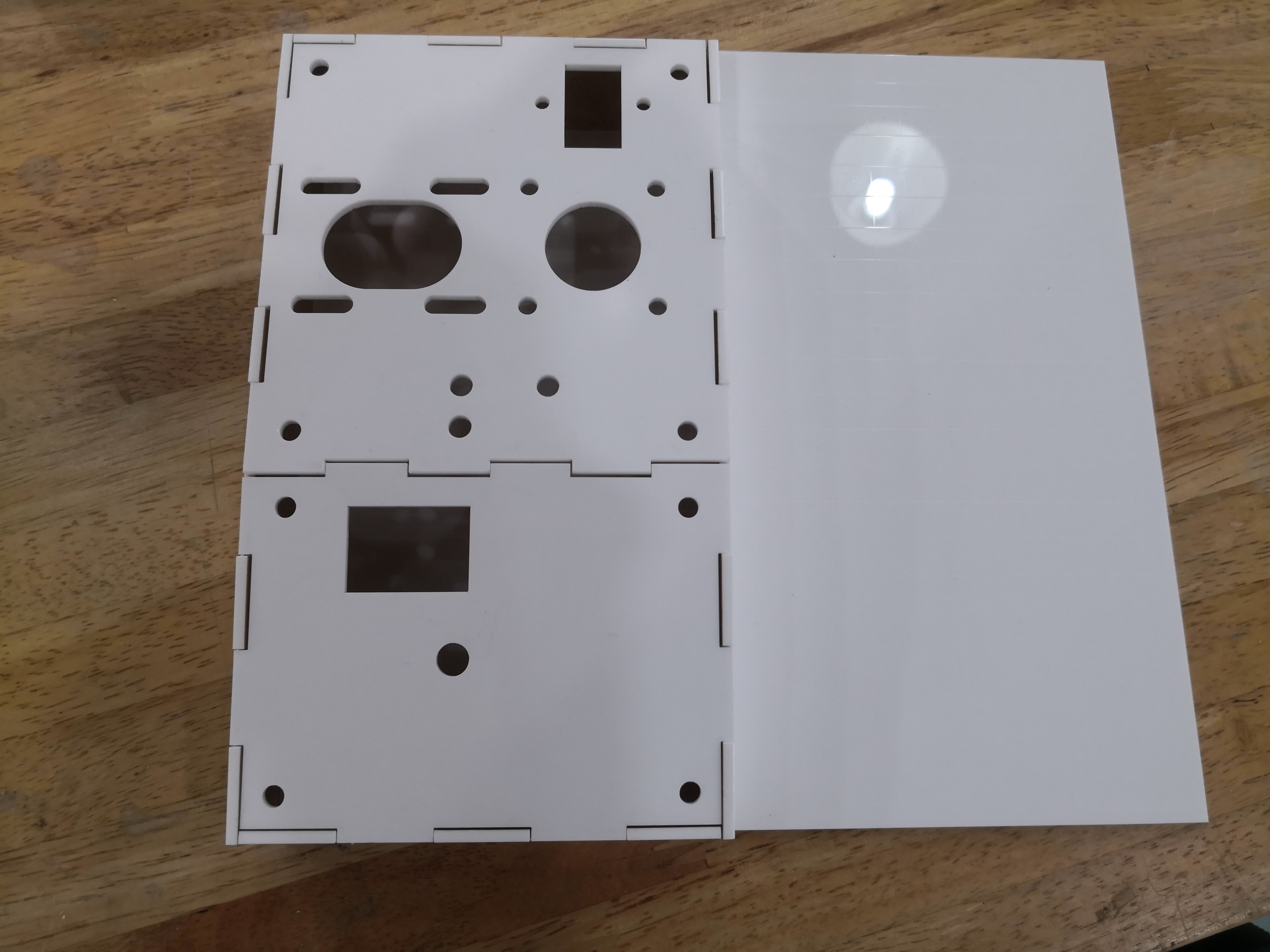
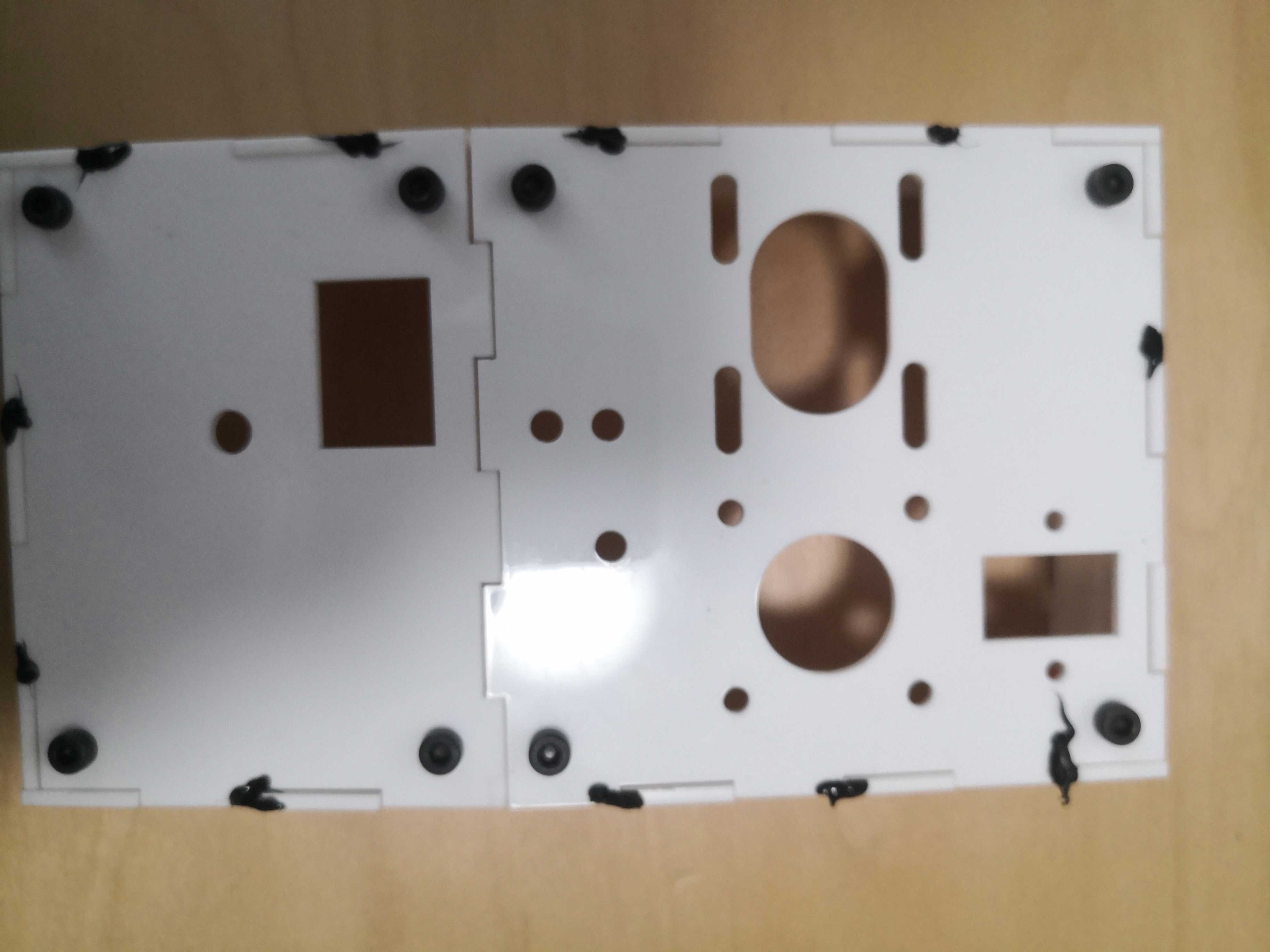
Final prototype-Laser cutting
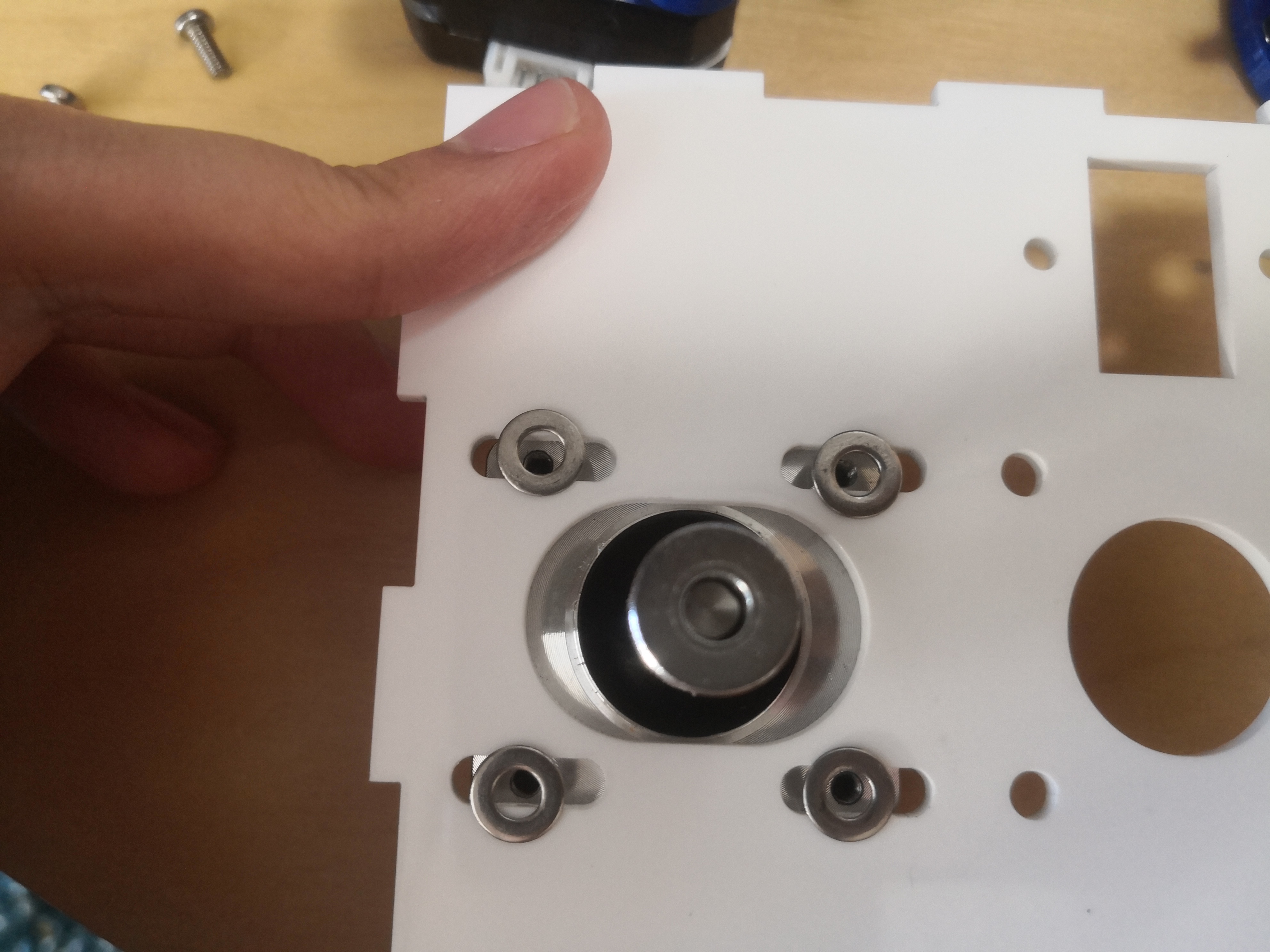
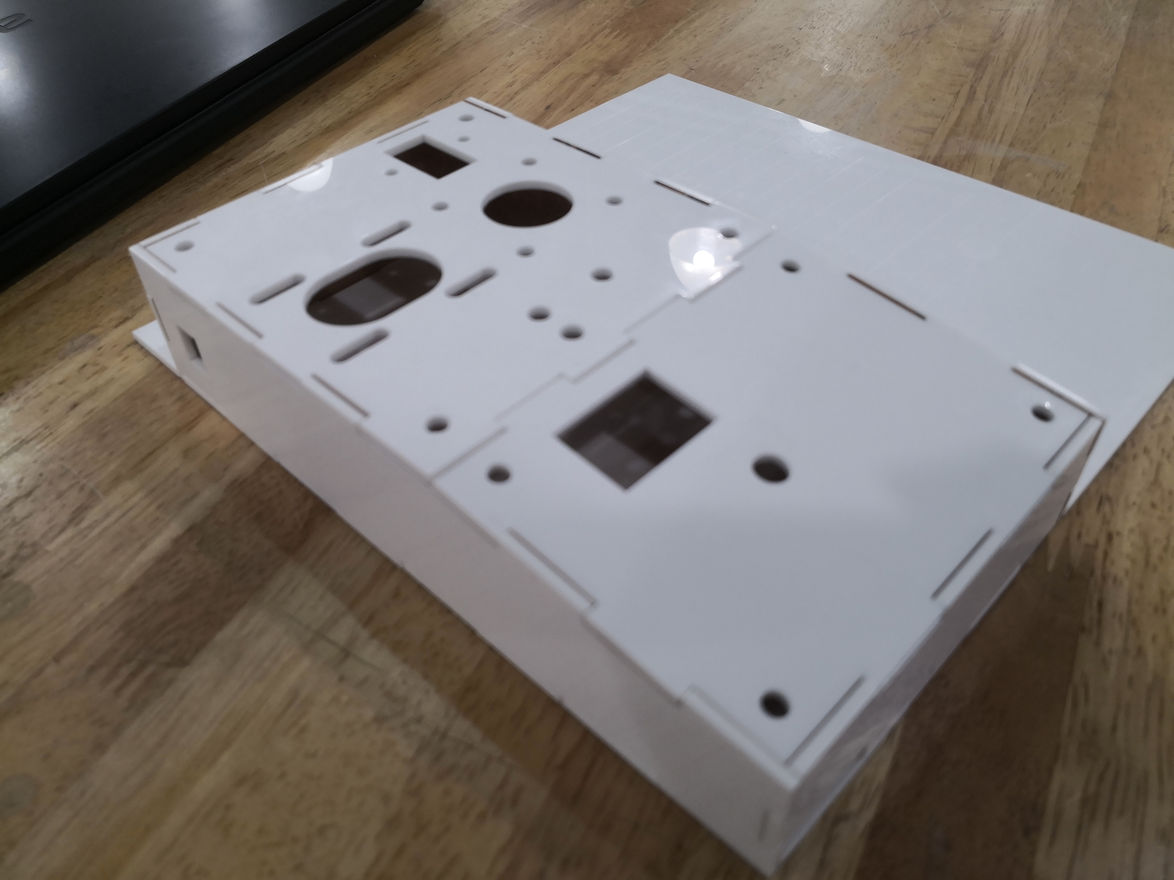
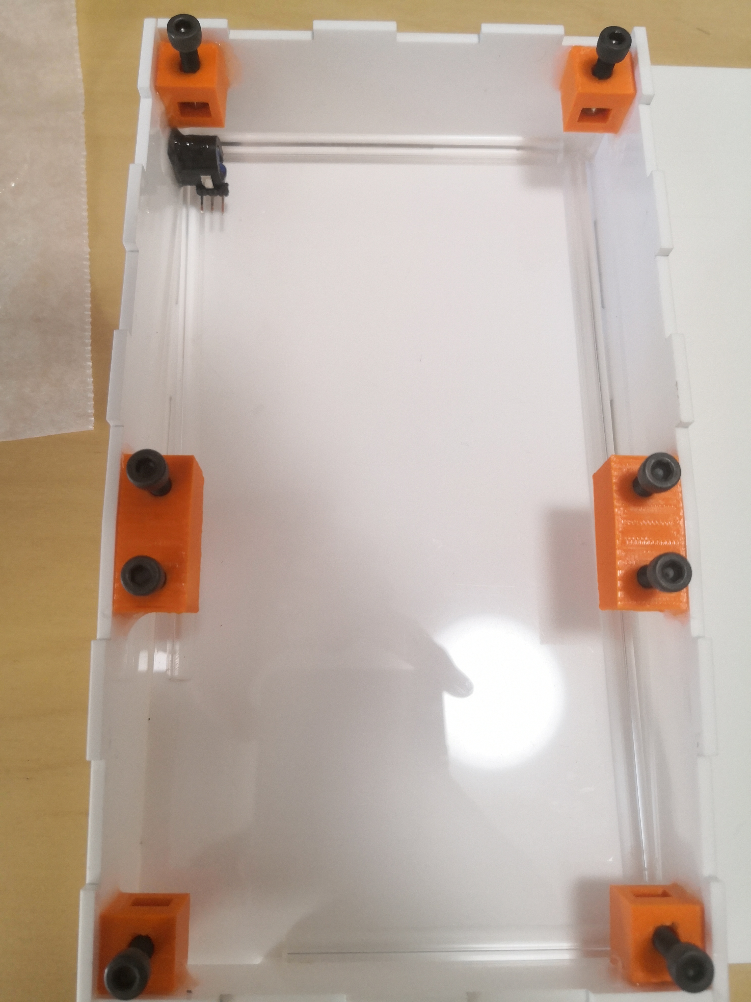
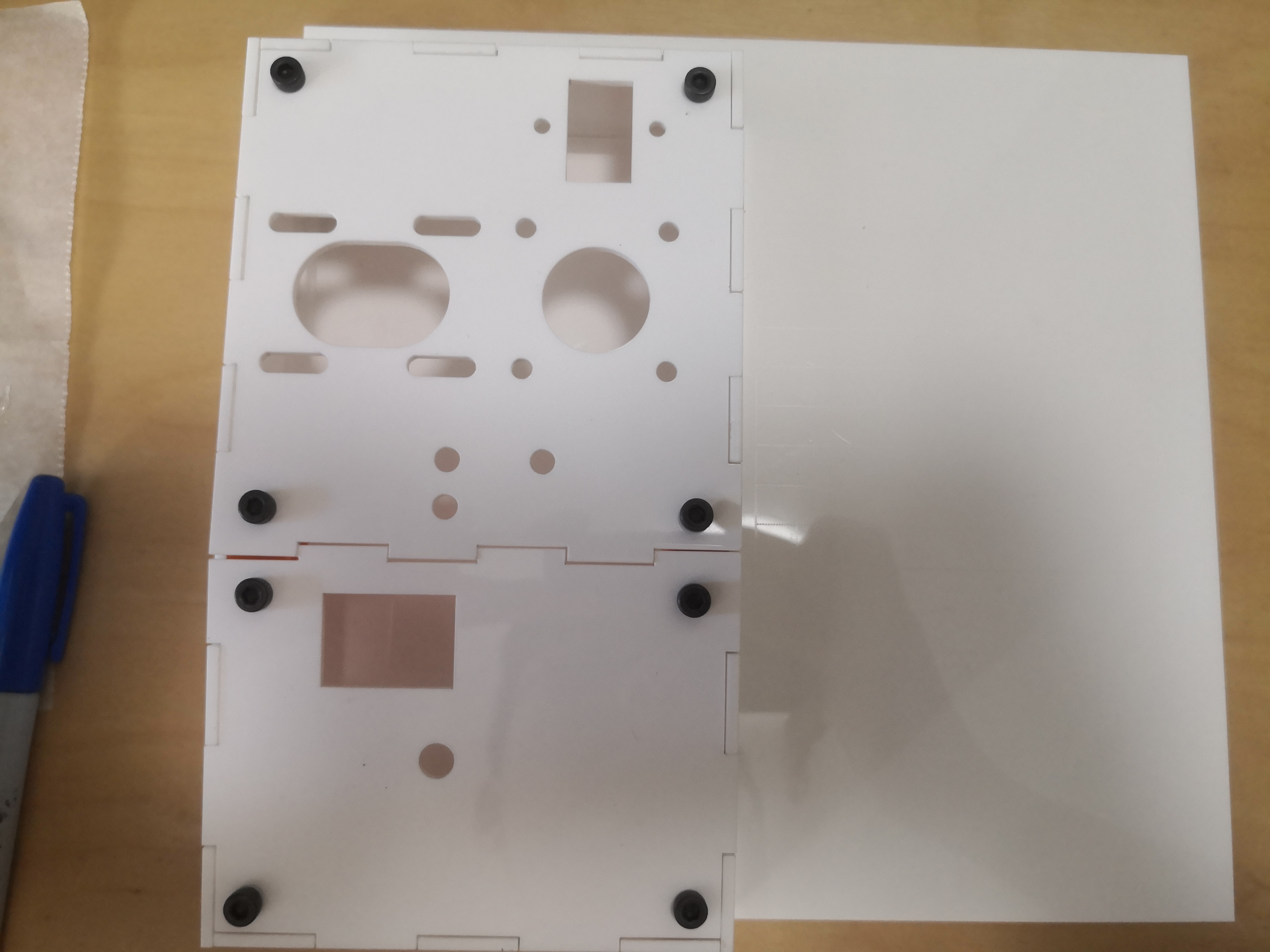
The sides of the base were cut on a laser cutter.
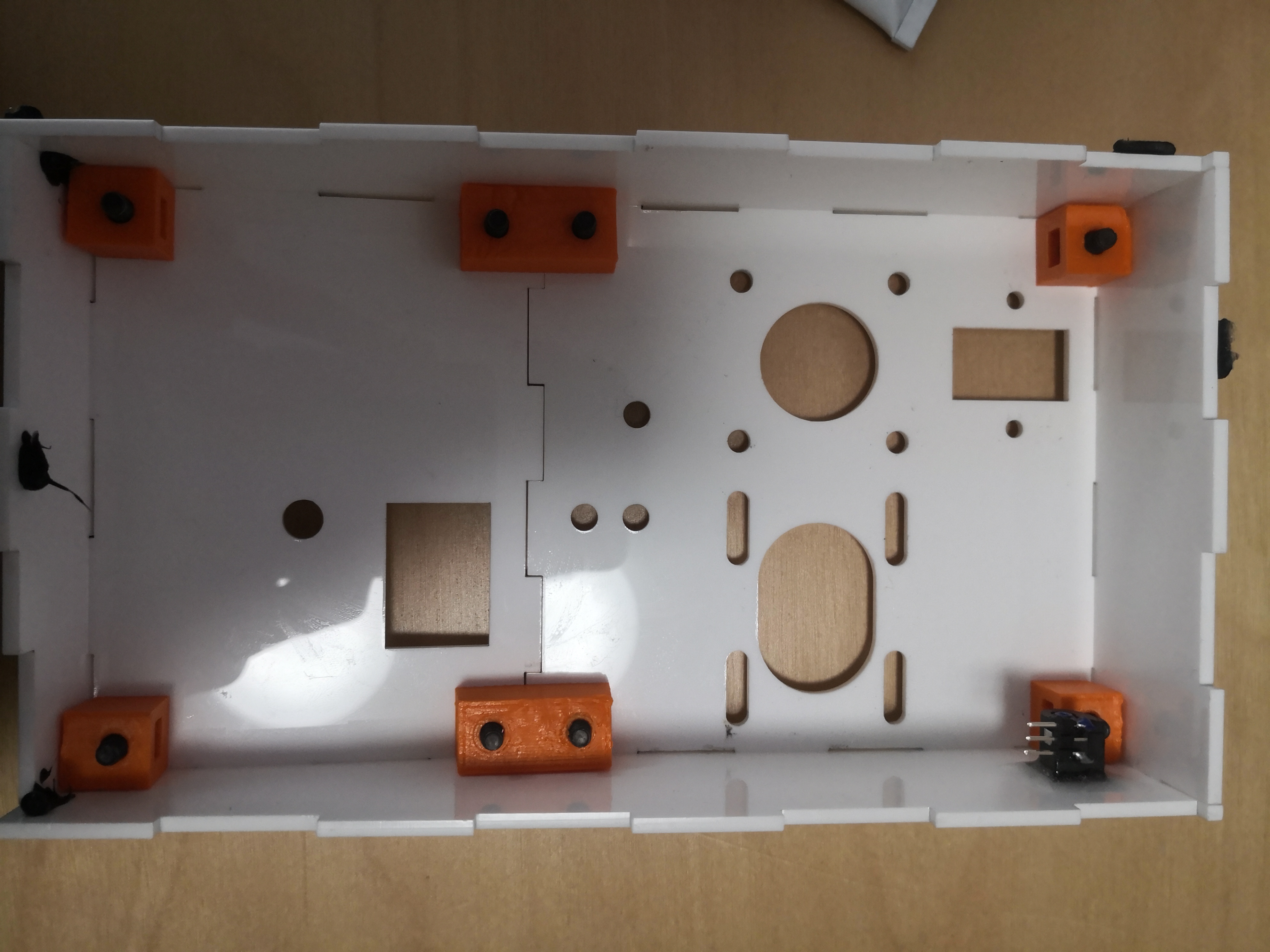
Test fitting the box.
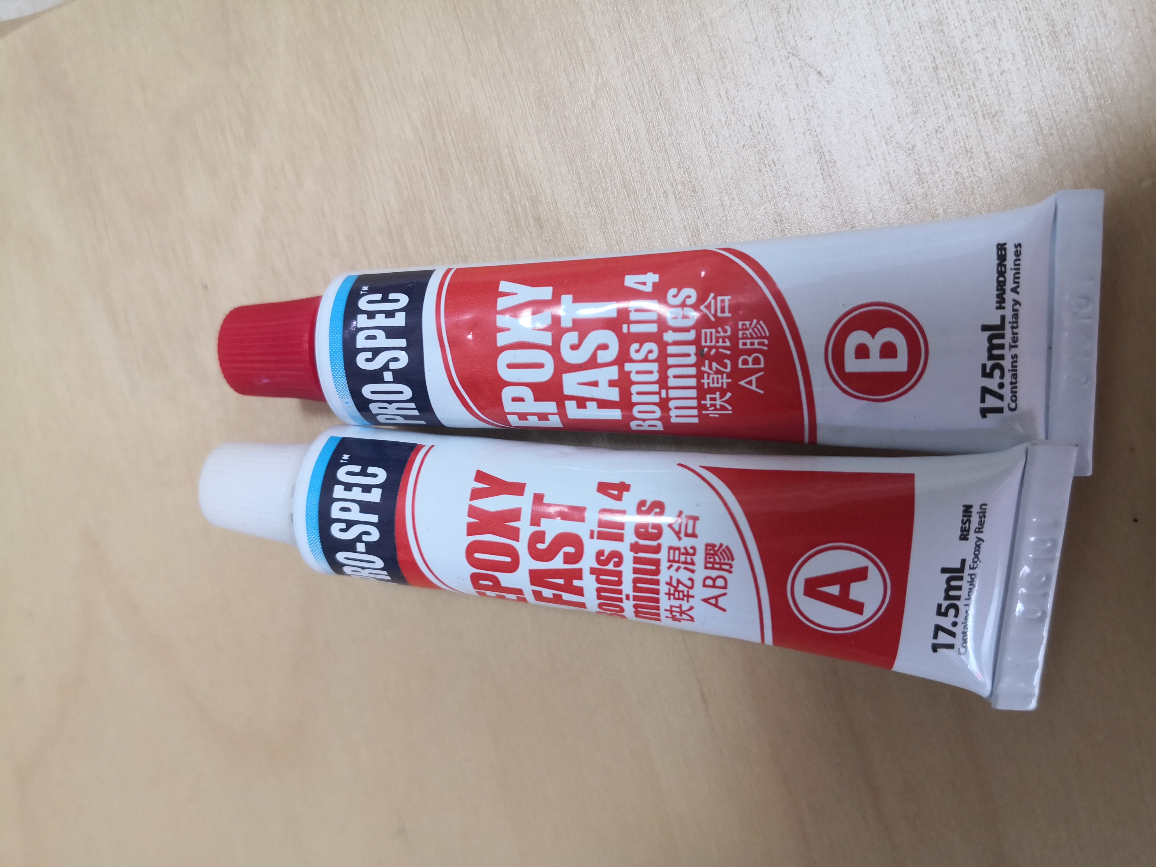
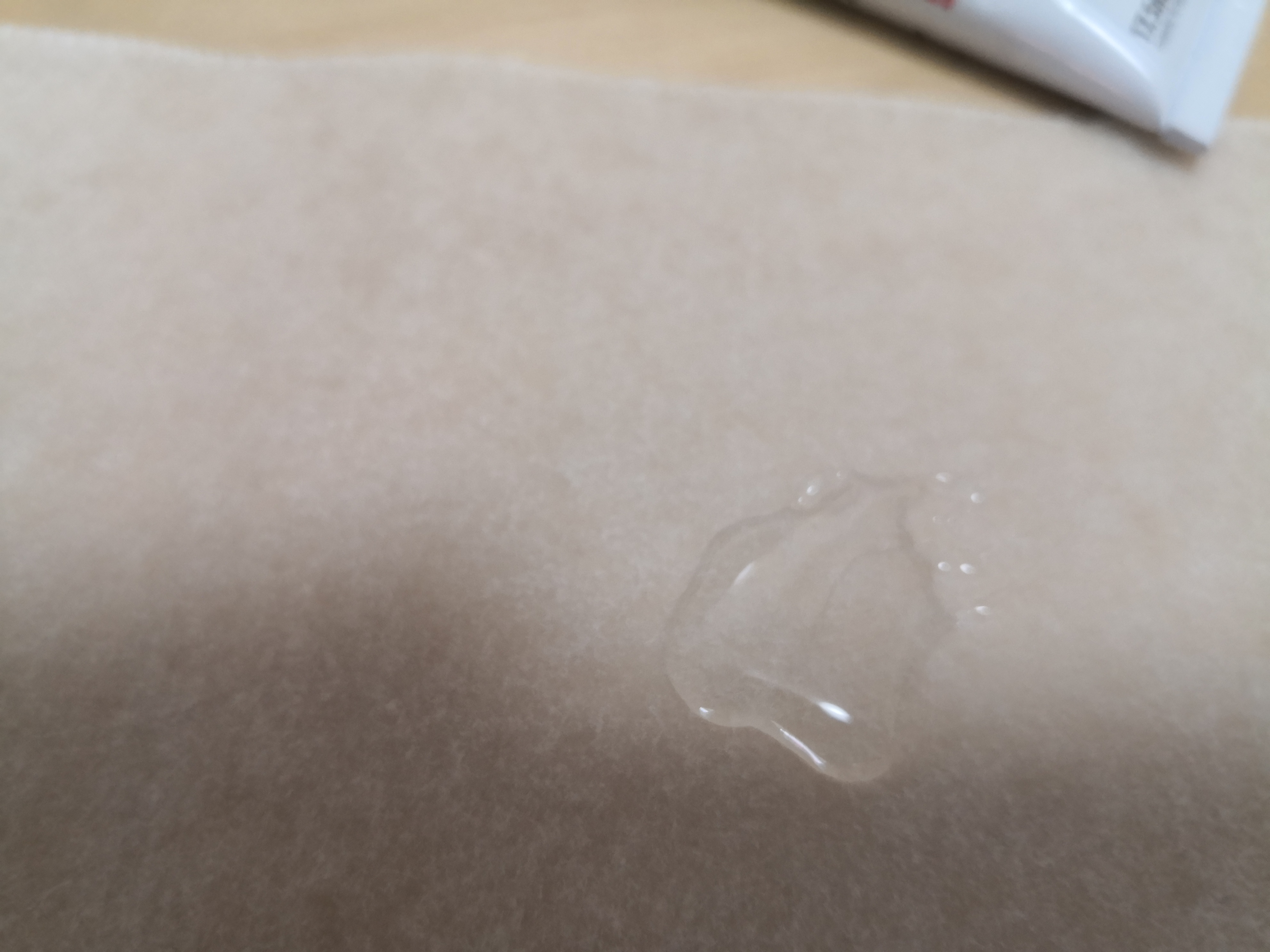
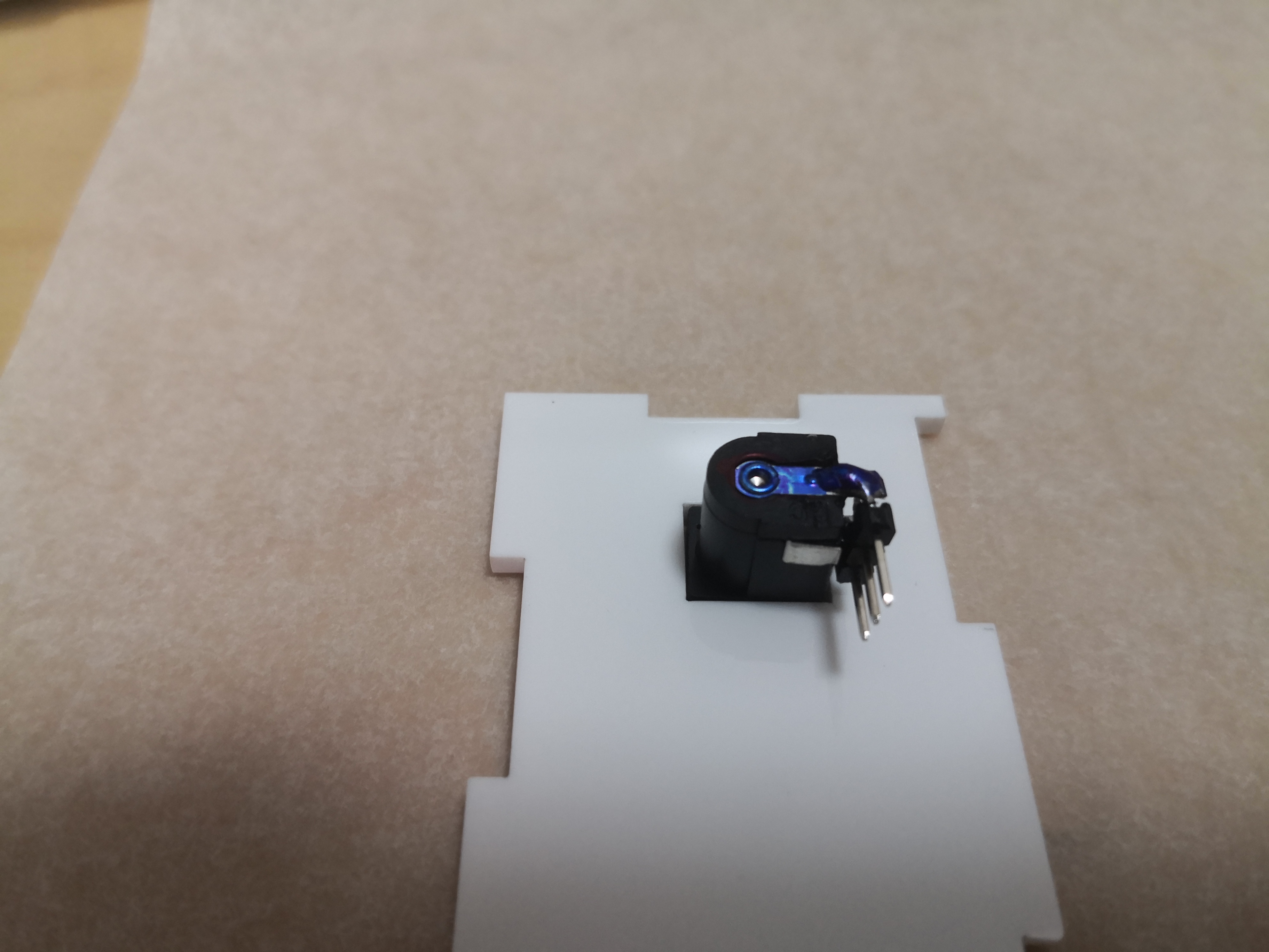
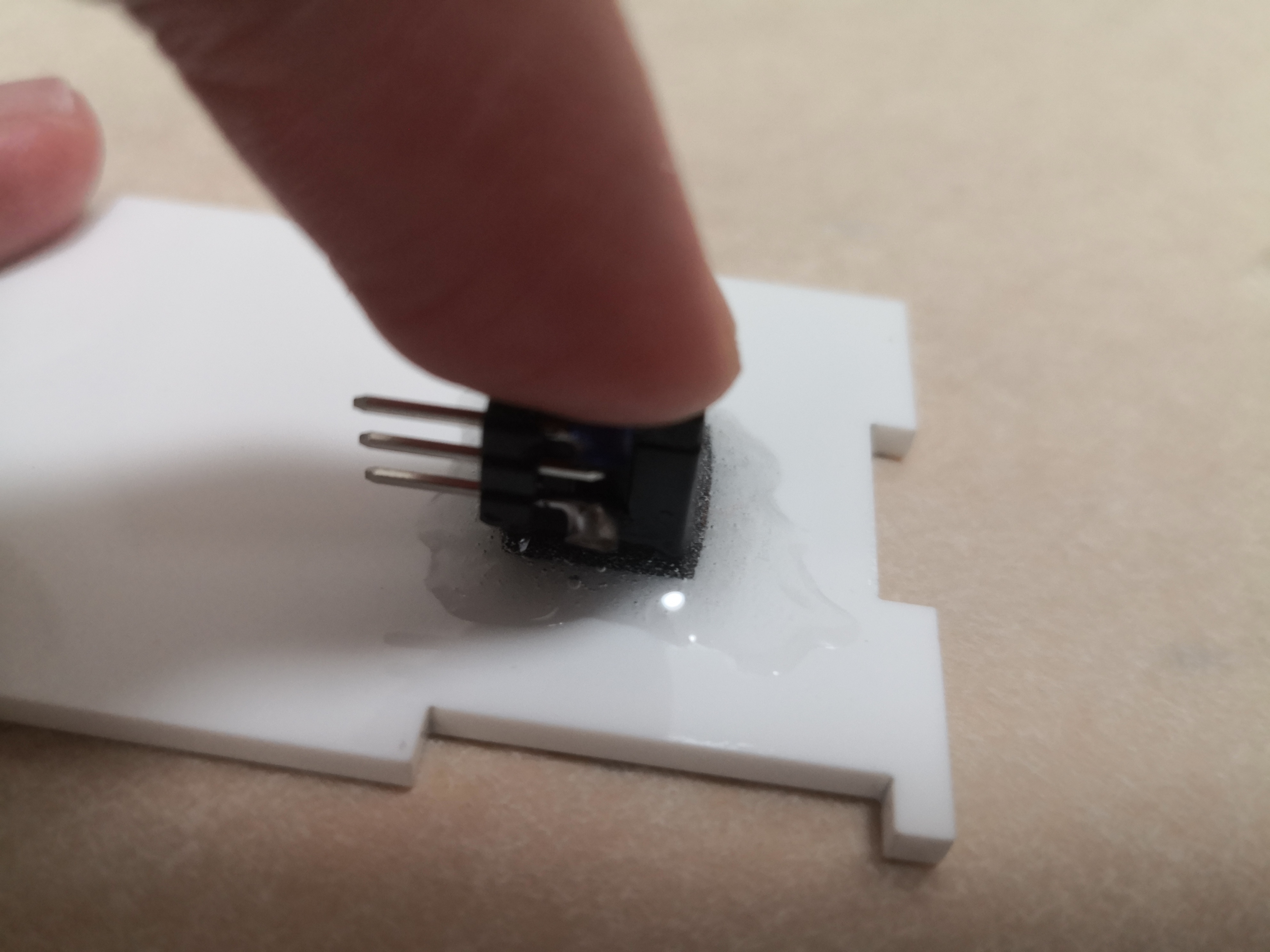
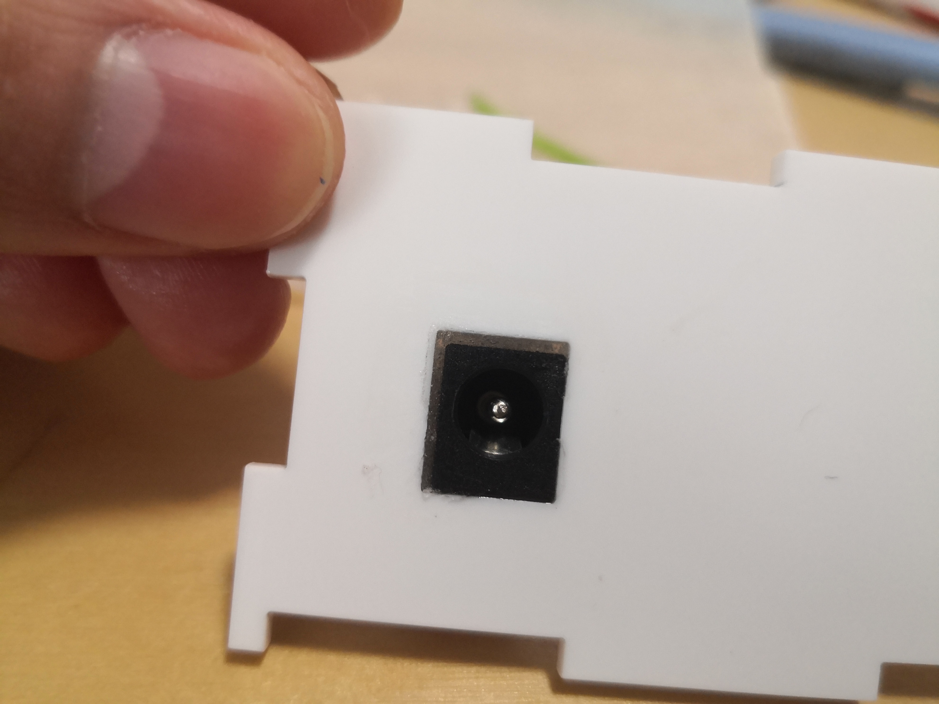
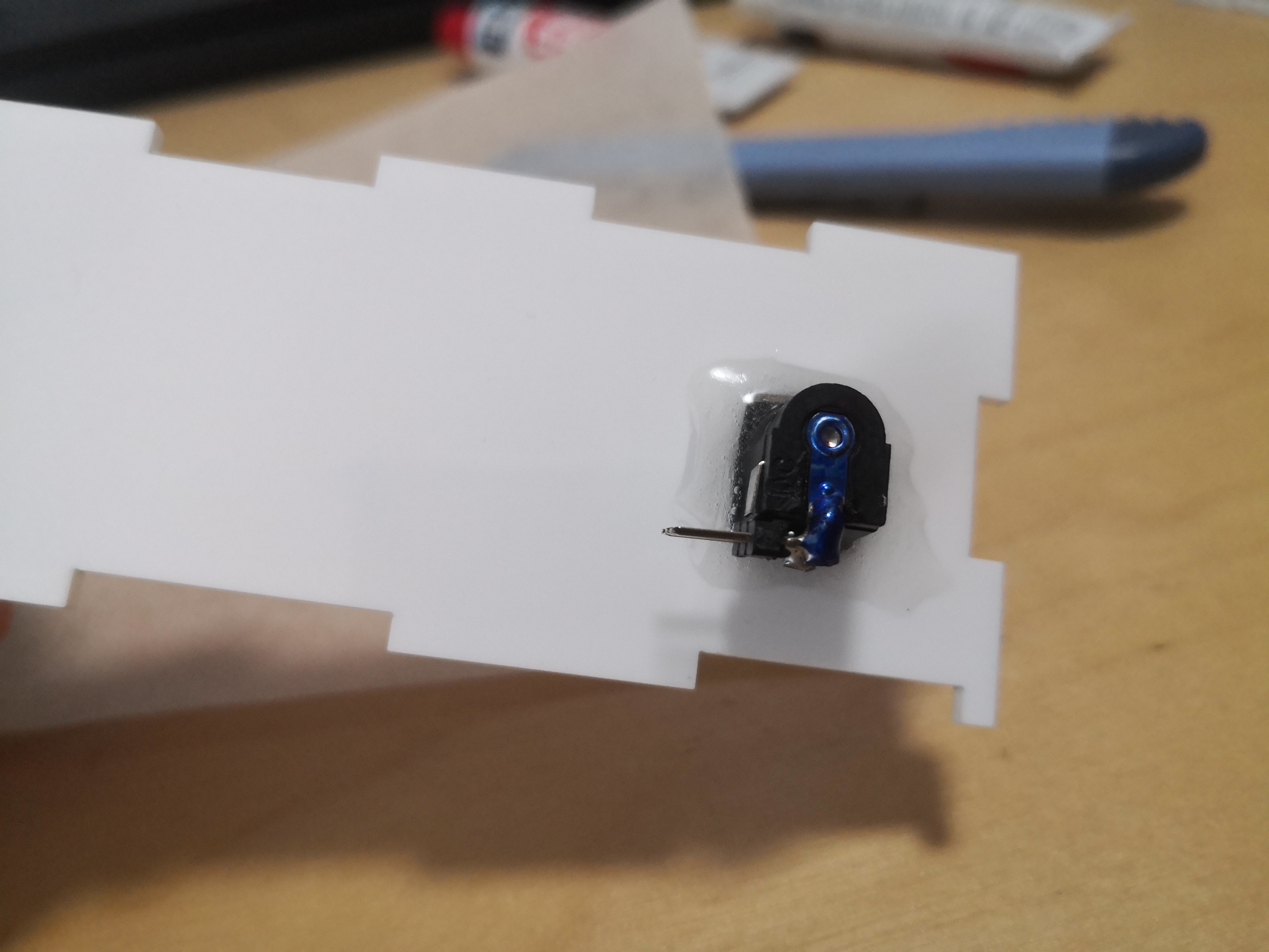
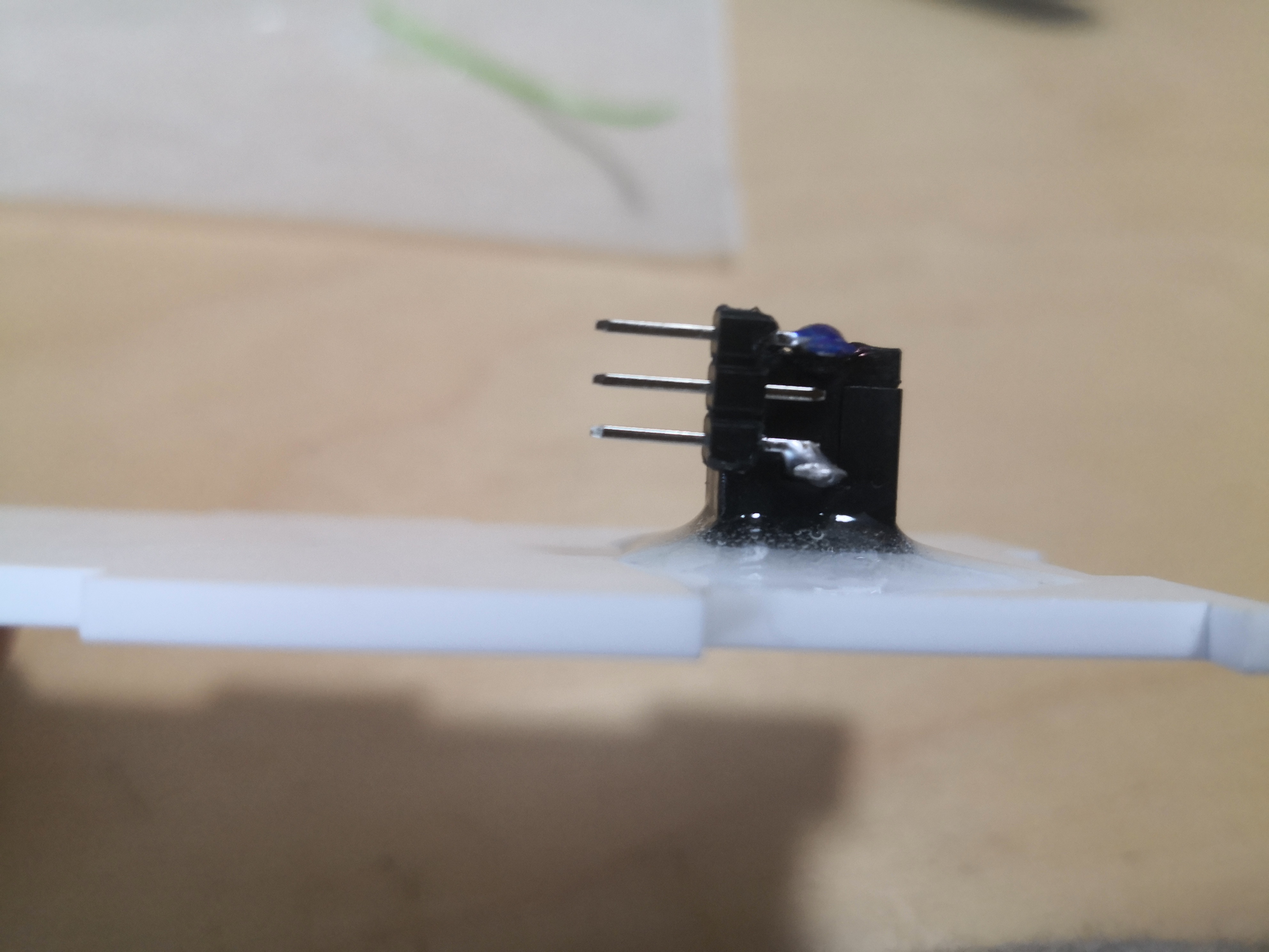
Epoxy is used to glue the 3d printed parts to the acyrlic and the barrel jack to the box.
The barrel jack is glued on.
Hot glue is used to hold the box together for now.
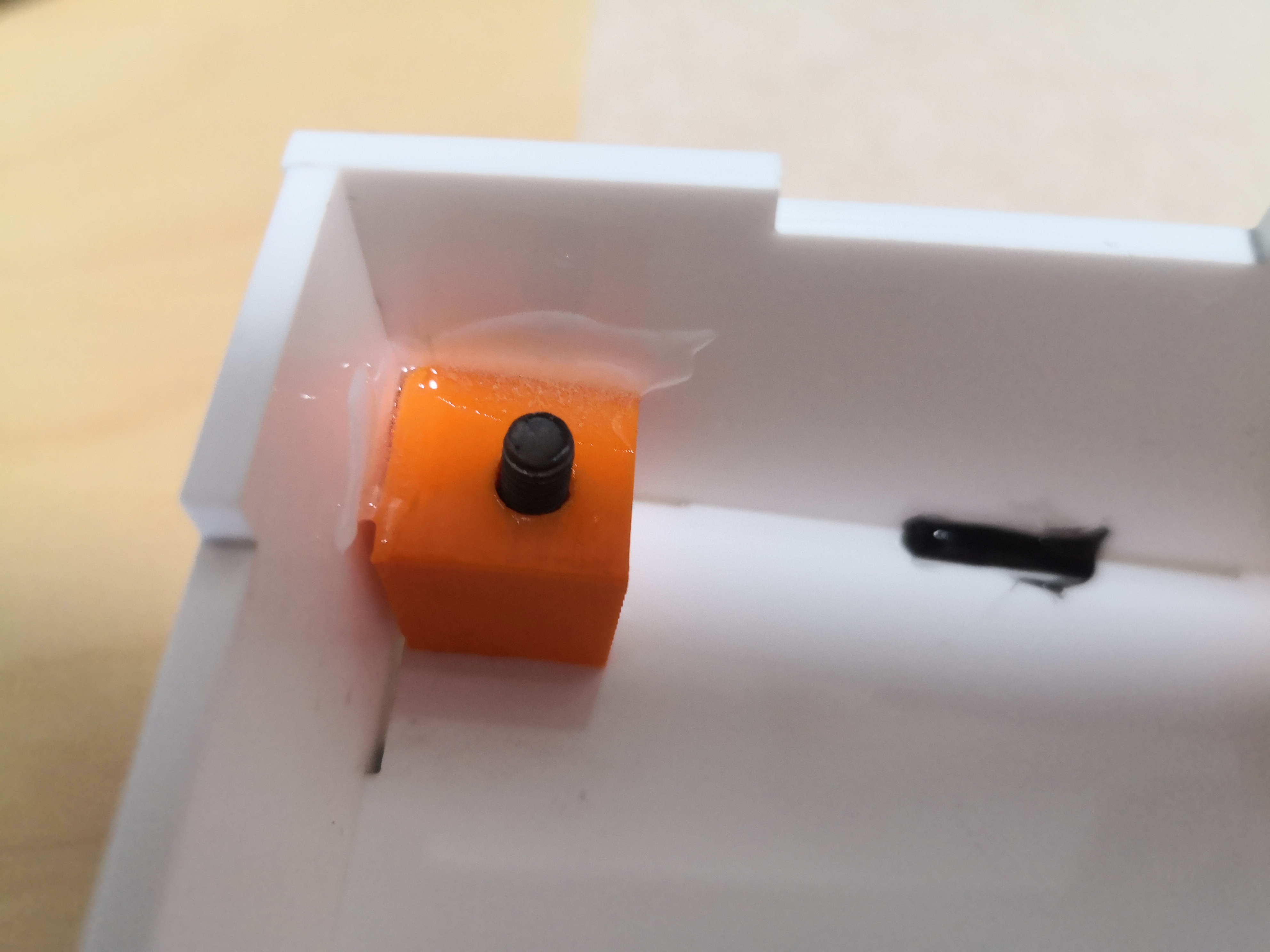
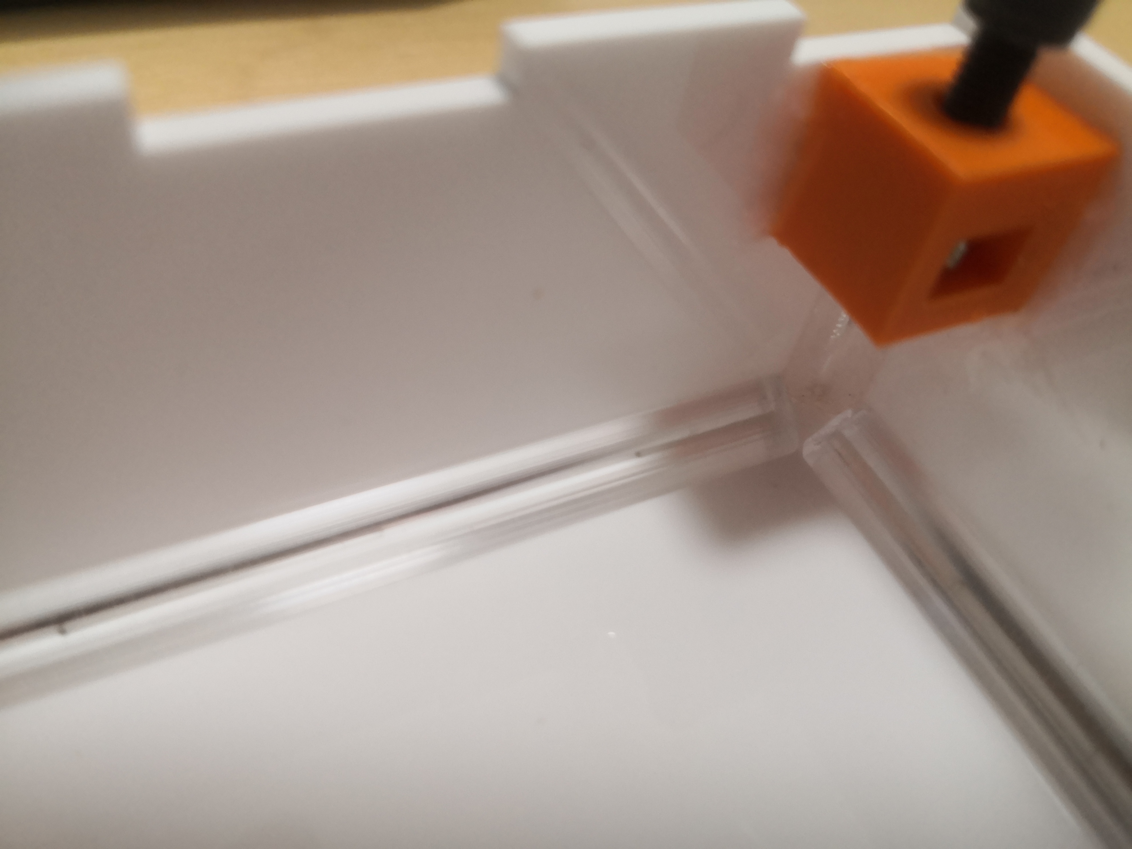
The 3d printed parts that allow the lid to screw on are glued.
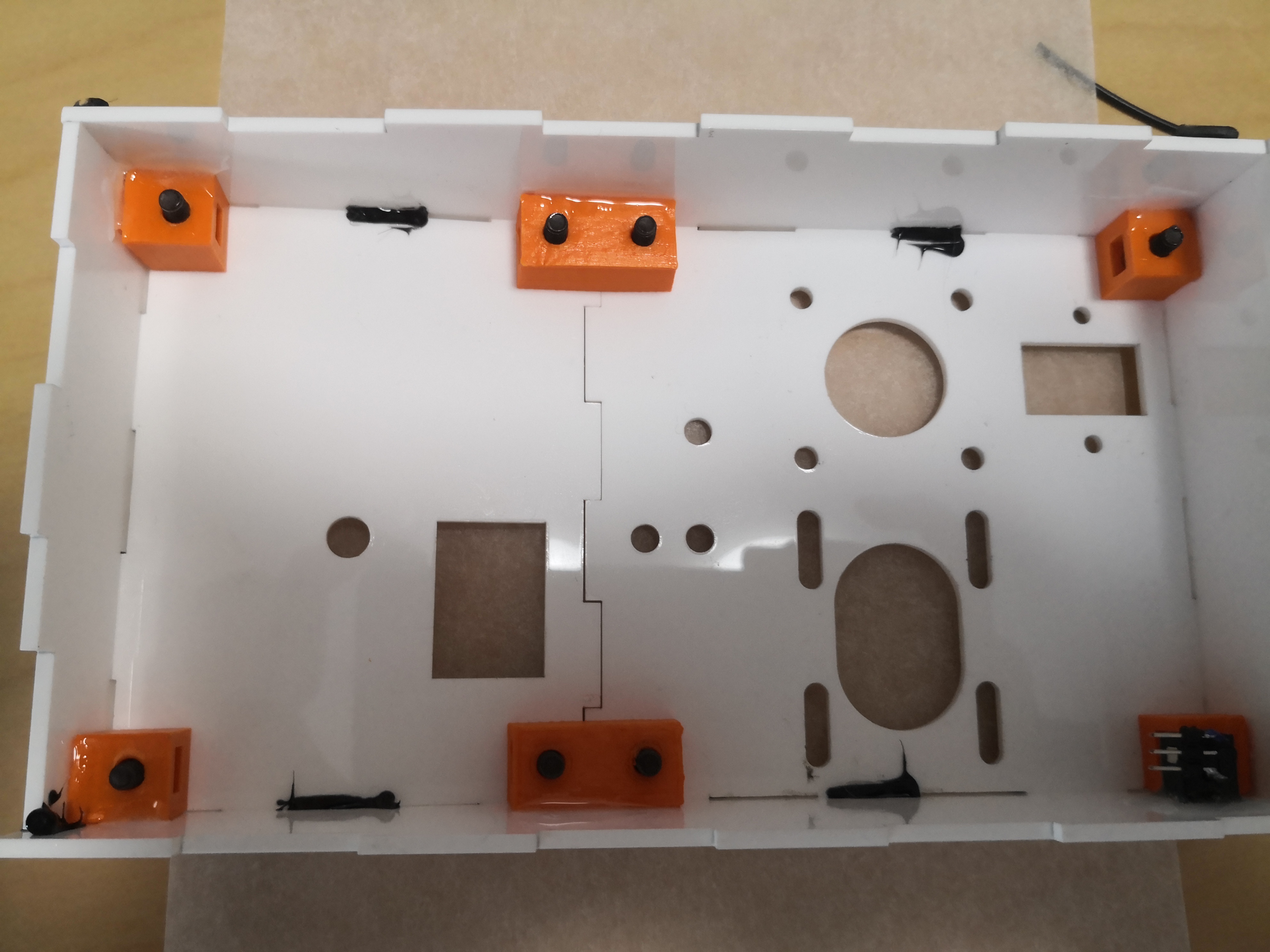
Acyrlic triangles are measured and cut.
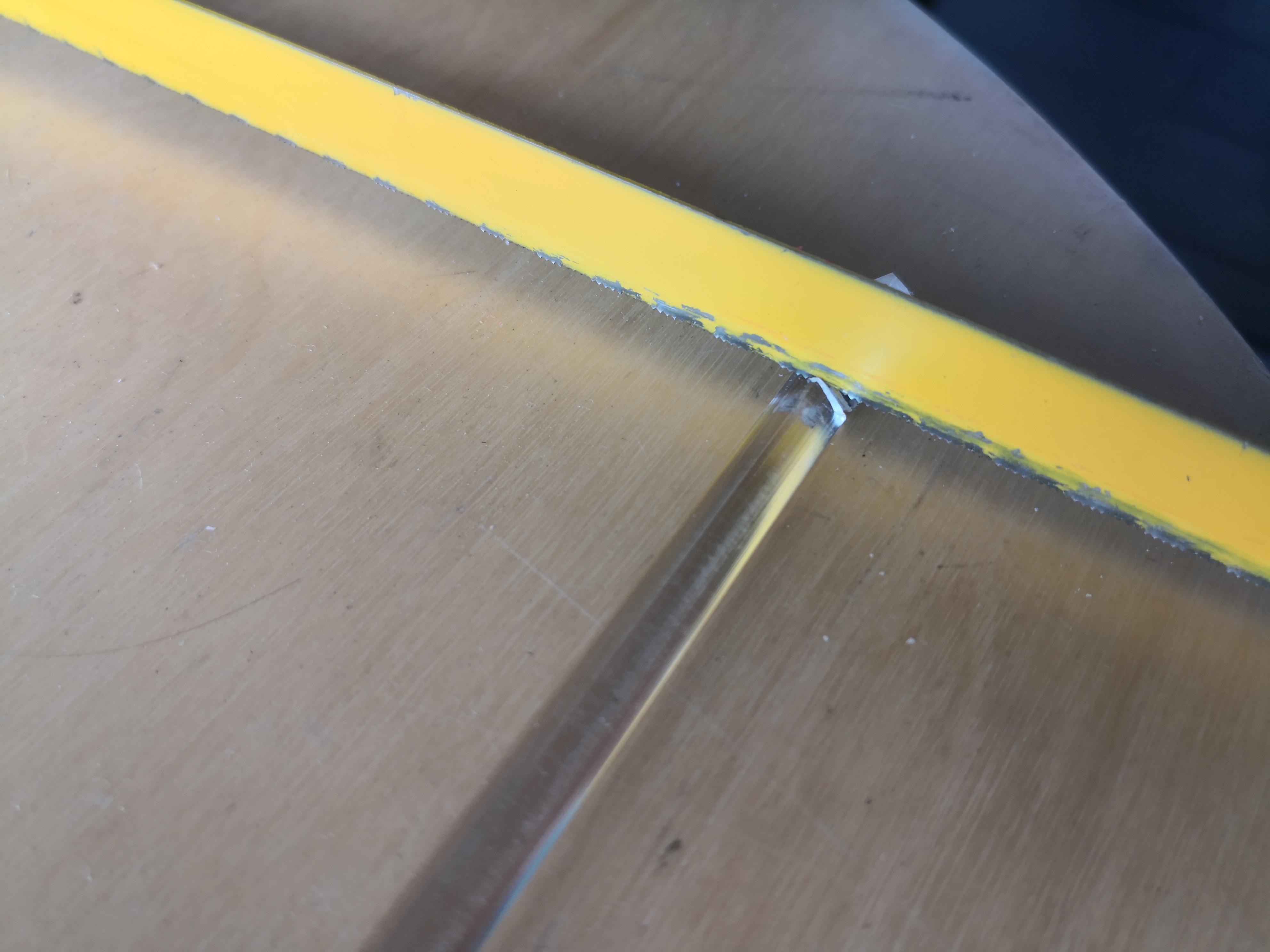
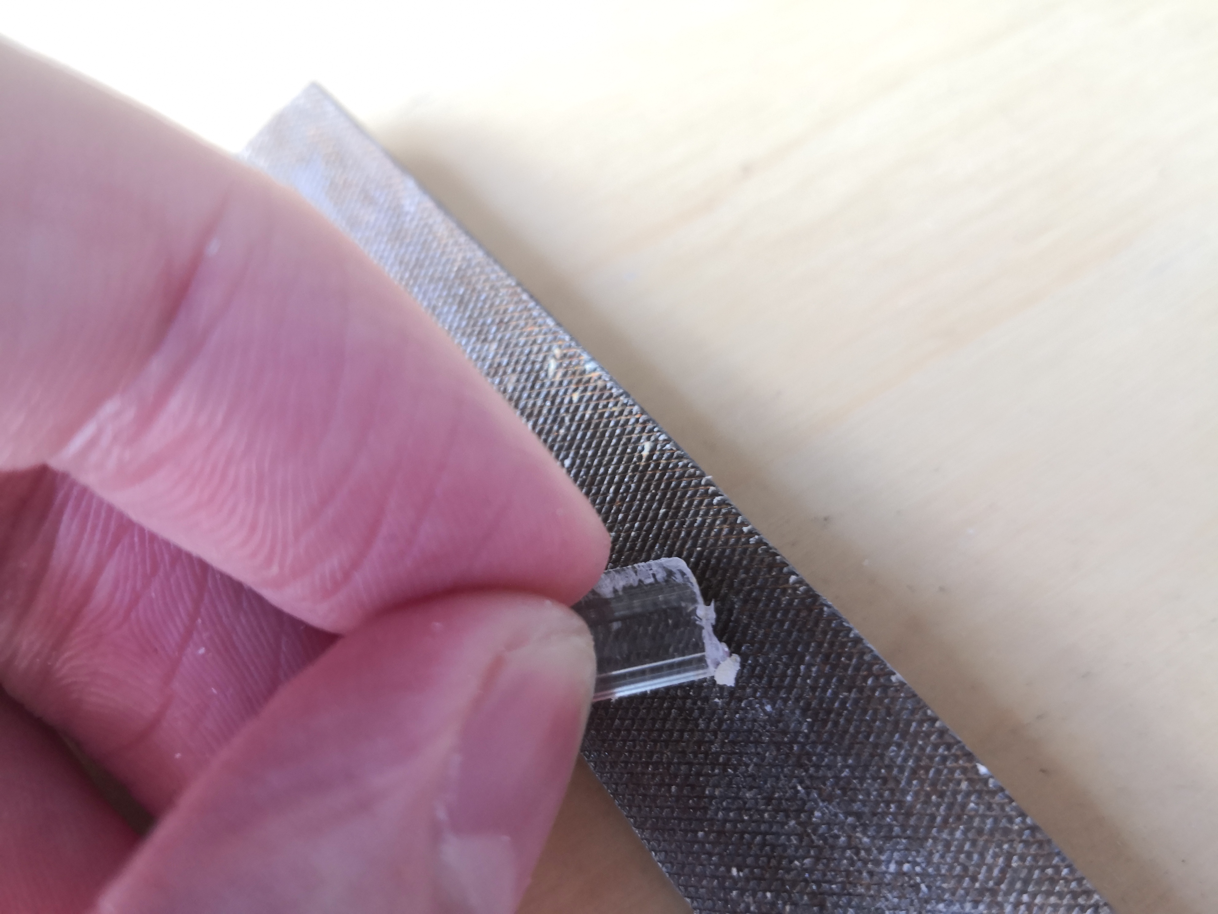
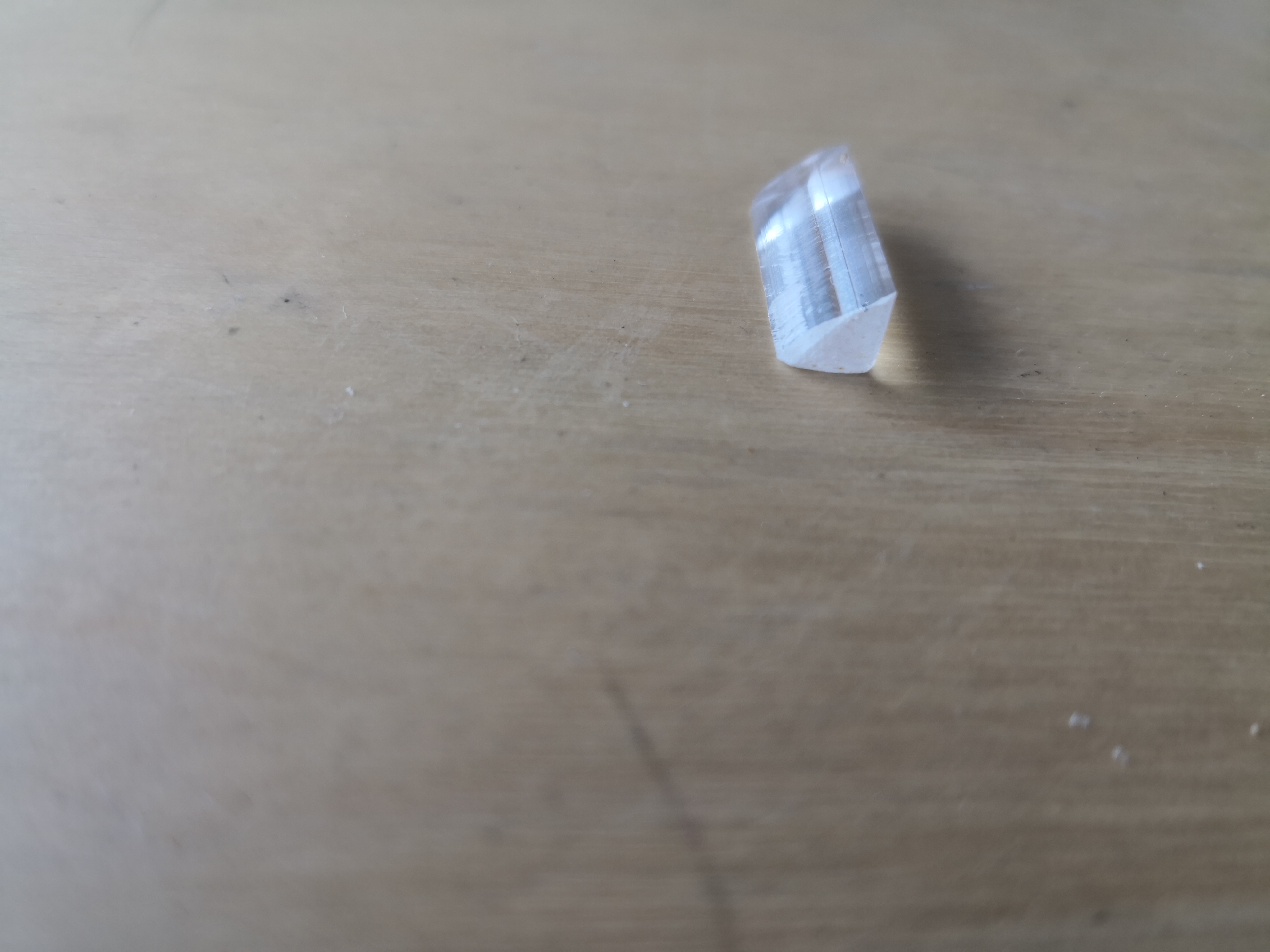
The acyrlic triangles are glued on using chlorofoam.
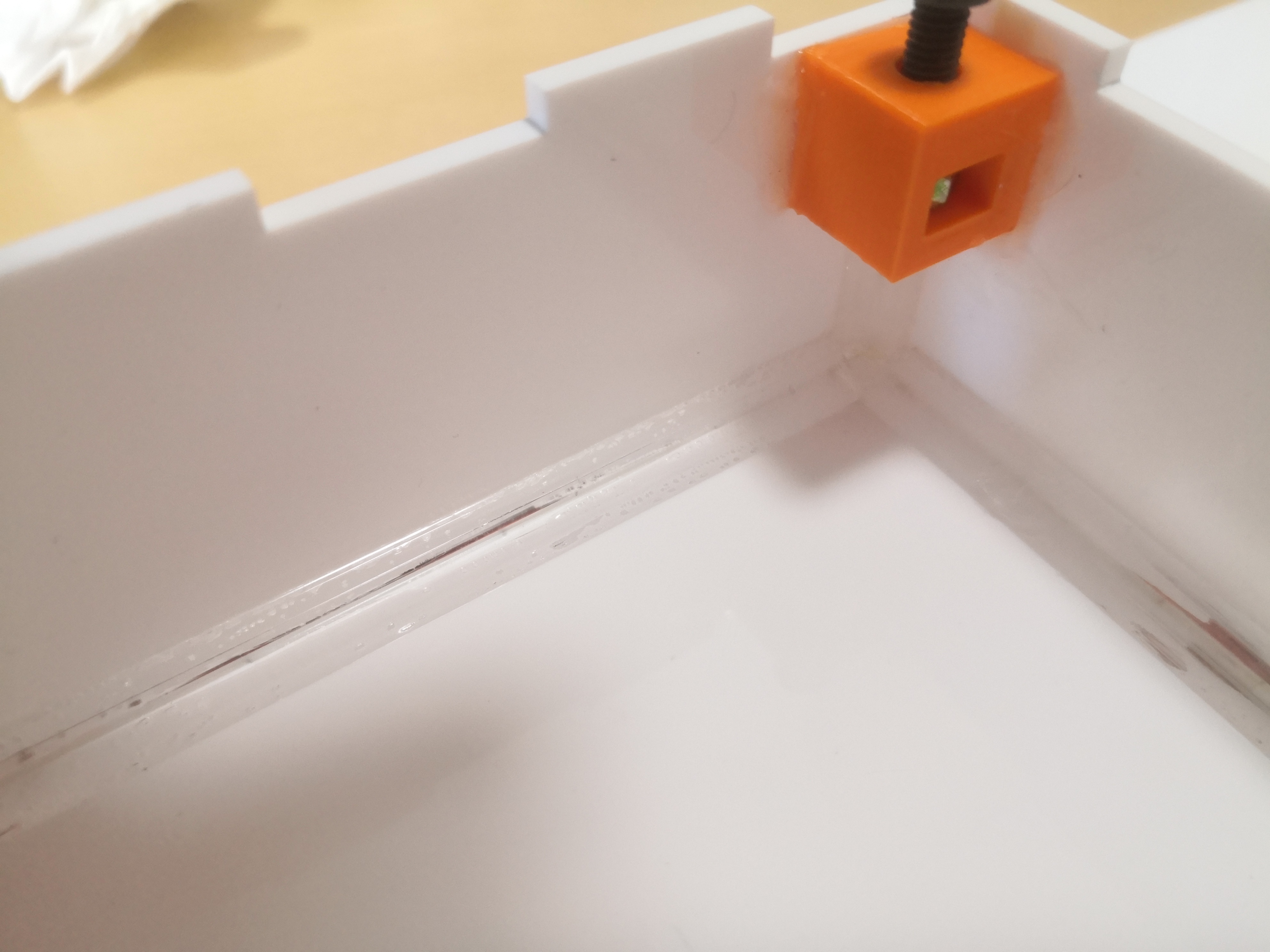
The box is finished.
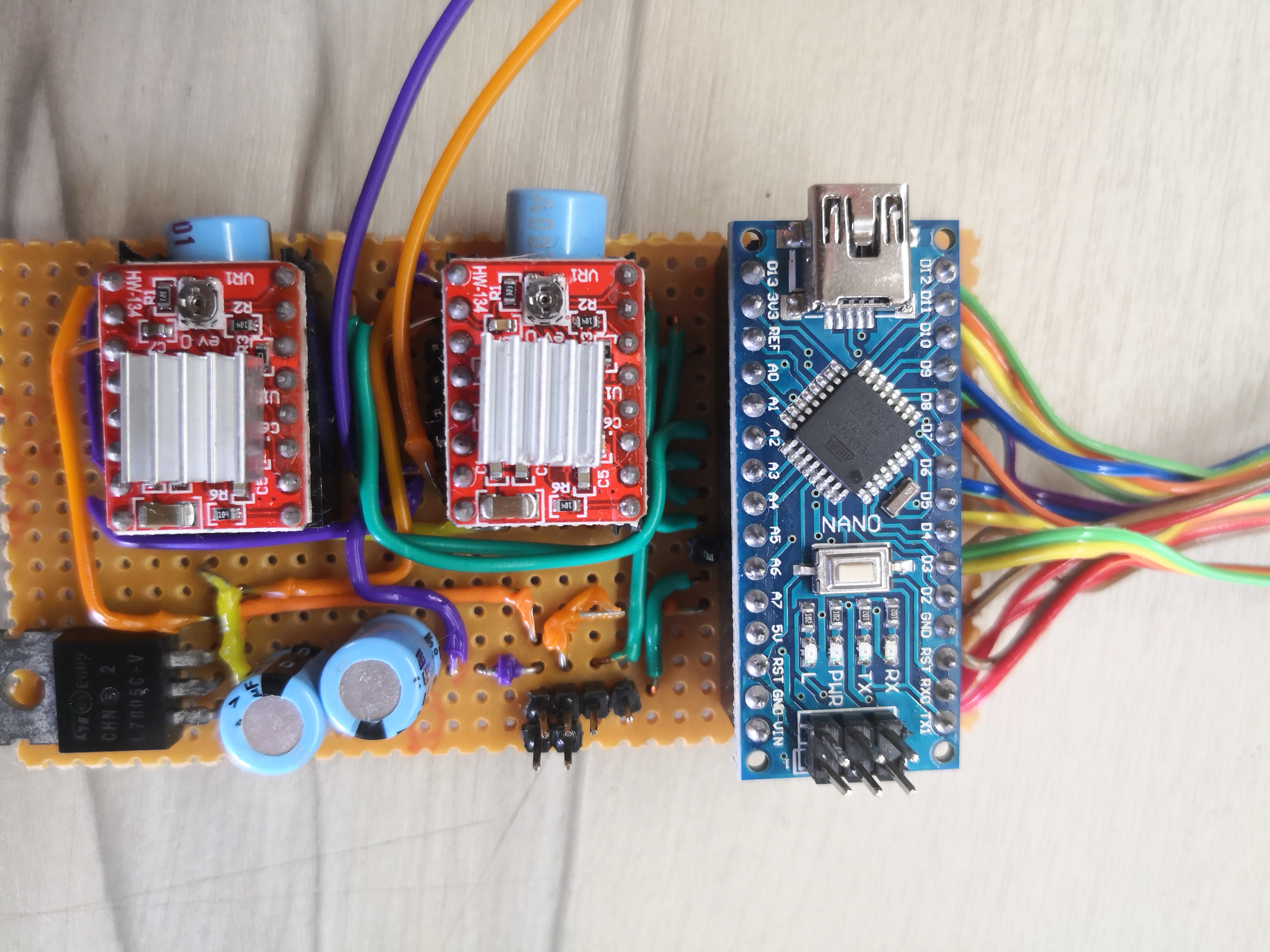
Final prototype-Electronics
Below is the schematic for the pen plotter drawn in Kicad.
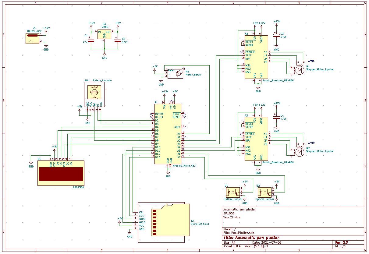
Click here to download Kicad project.
The parts are soldered onto a perfboard for a more permernant construction. Ribbon cables are used to connect to the OLED screen, rotory encoder and SD card.
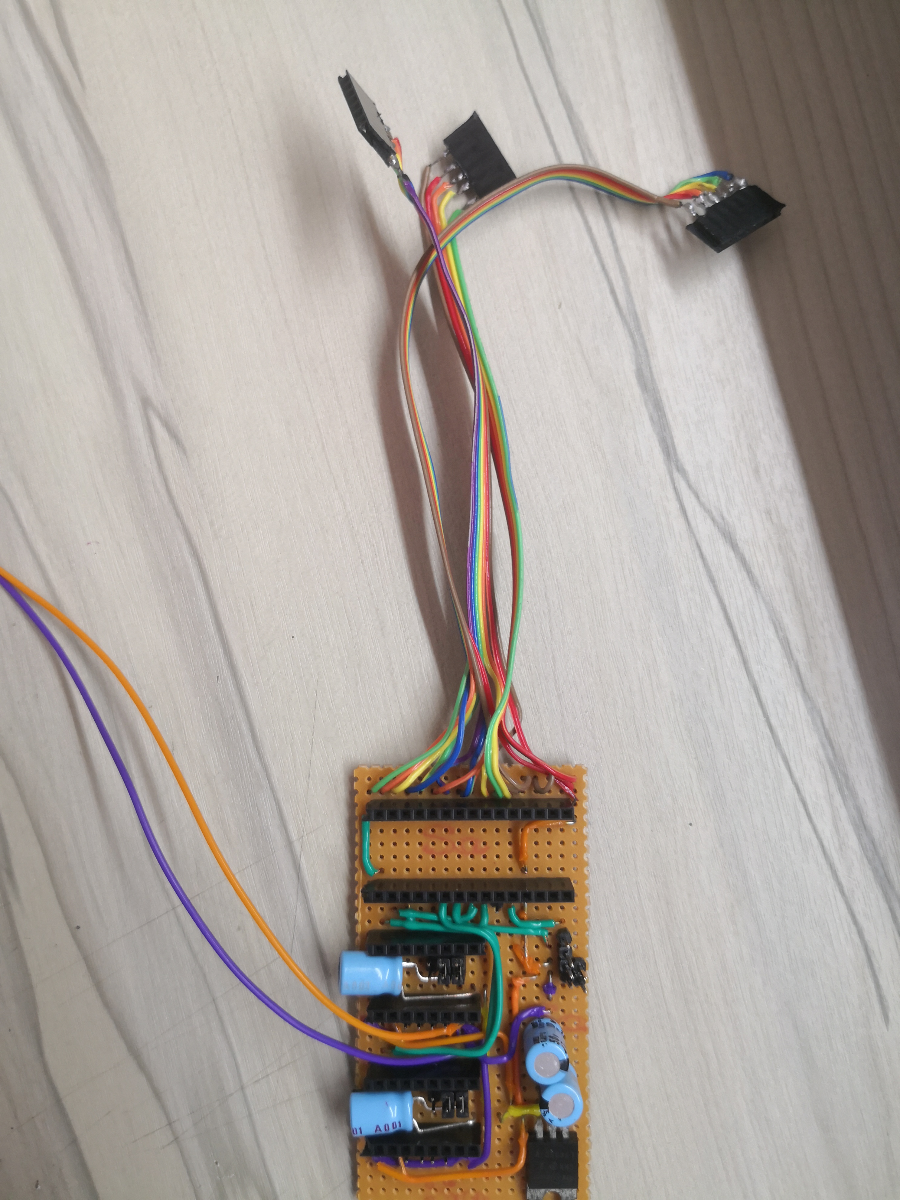
A close up of the soldered PCB
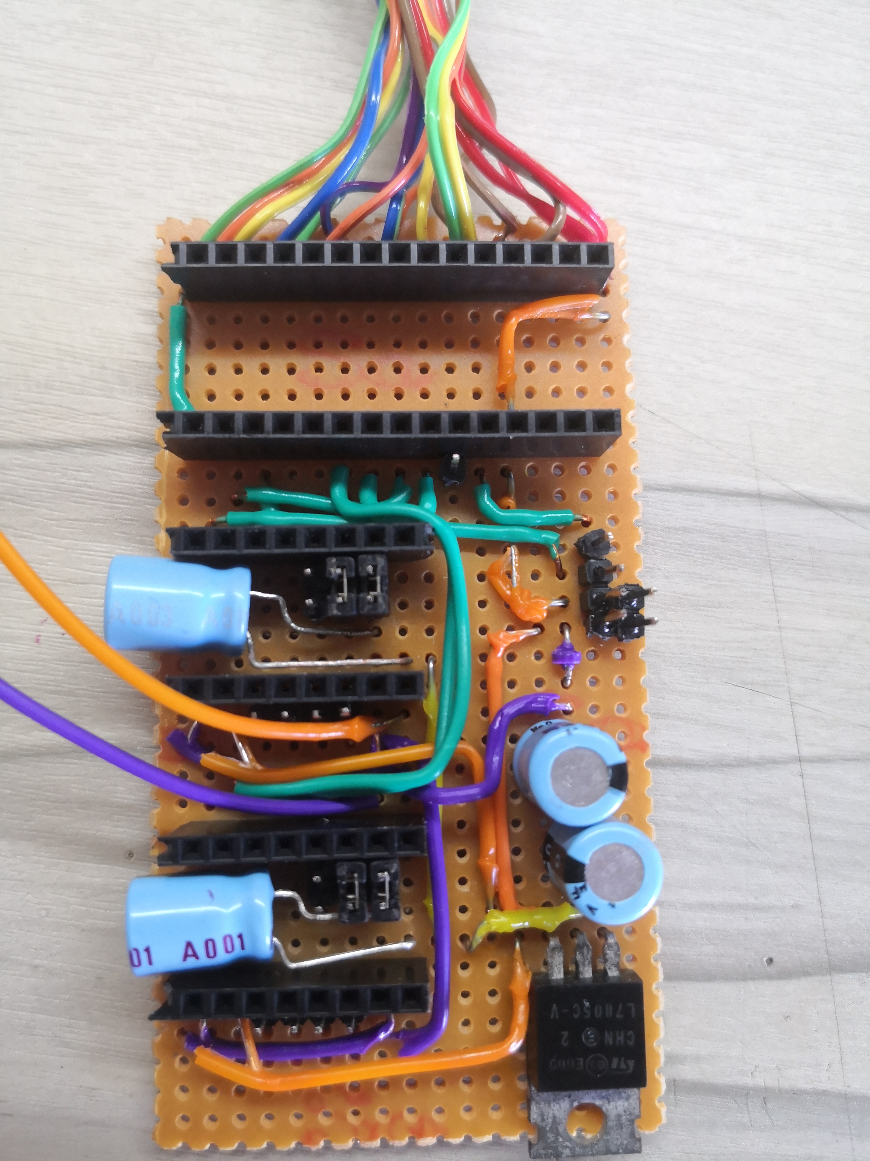
PCB after adding the microcontroller and motor drivers.
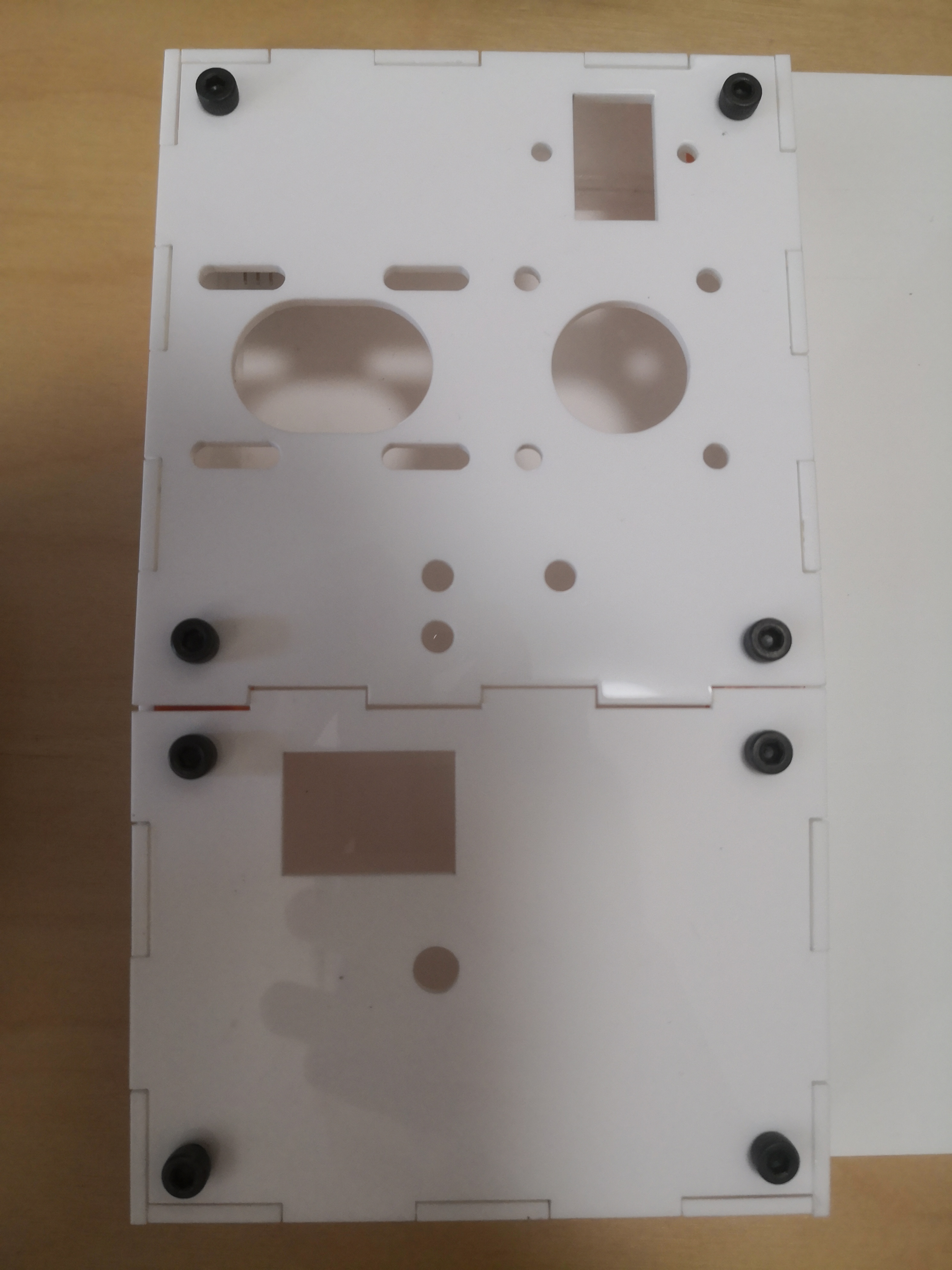
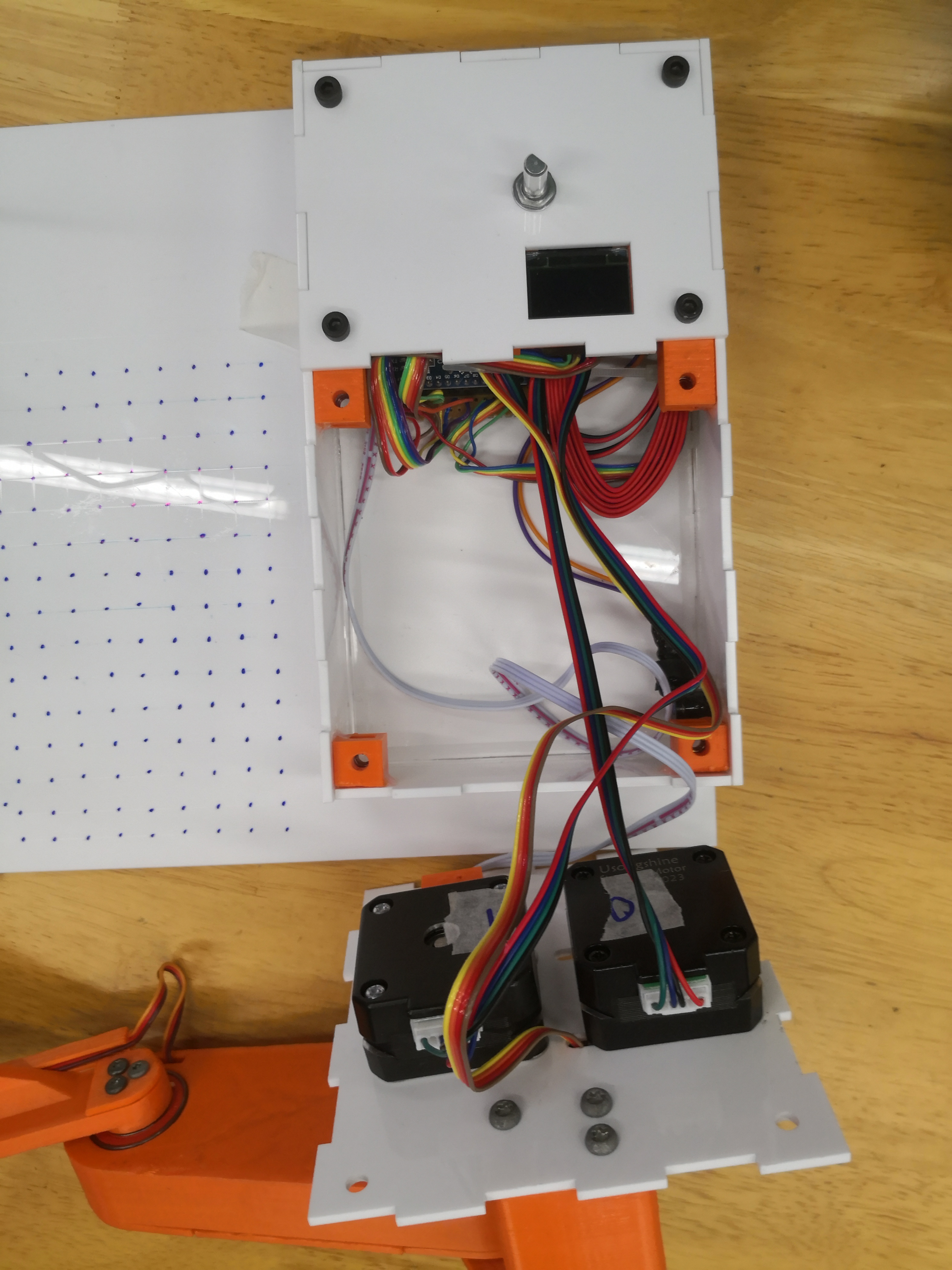
The PCB and SD card reader is mounted to the base.
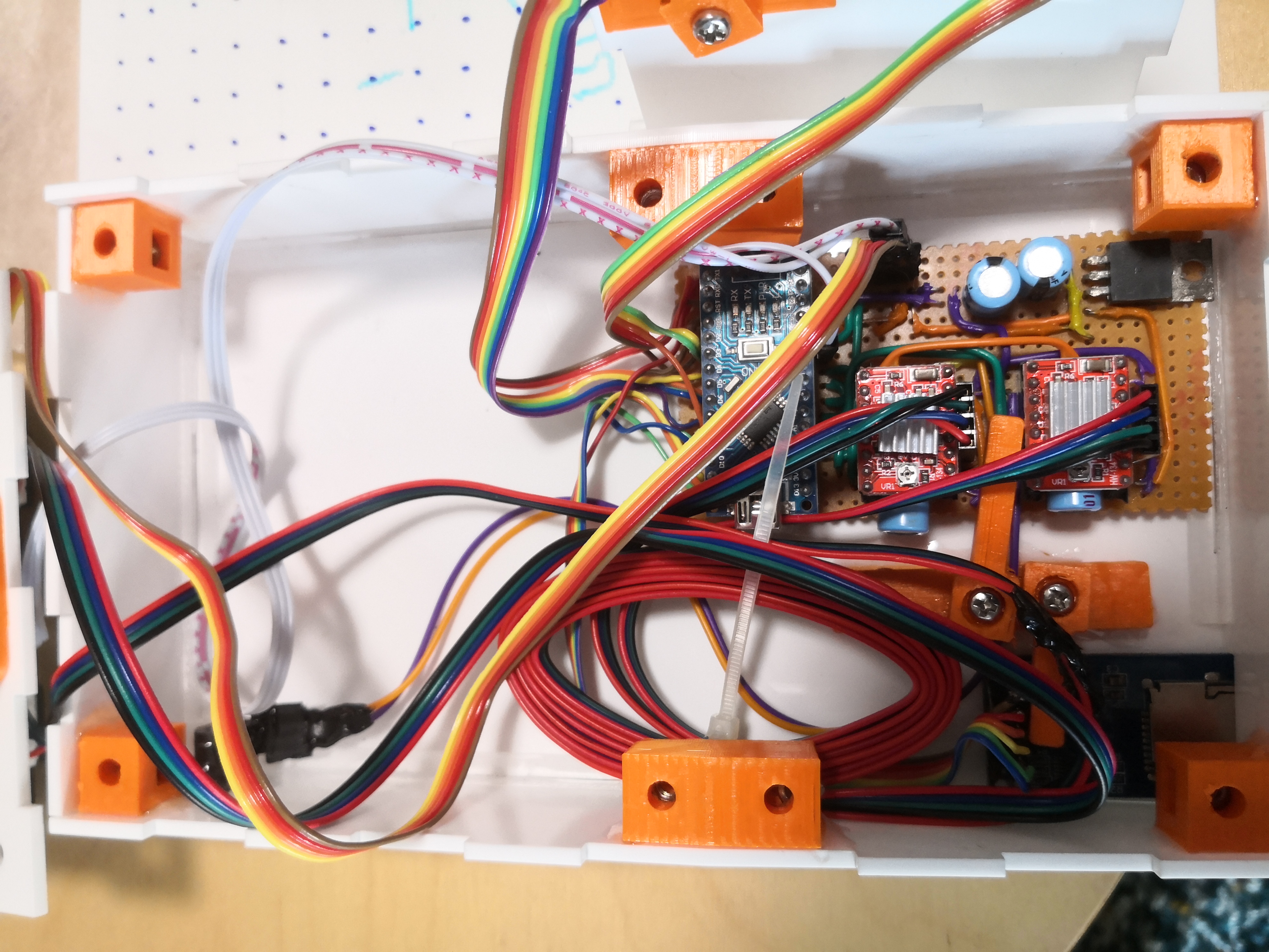
The Electronic components are clamped to the acyrlic.
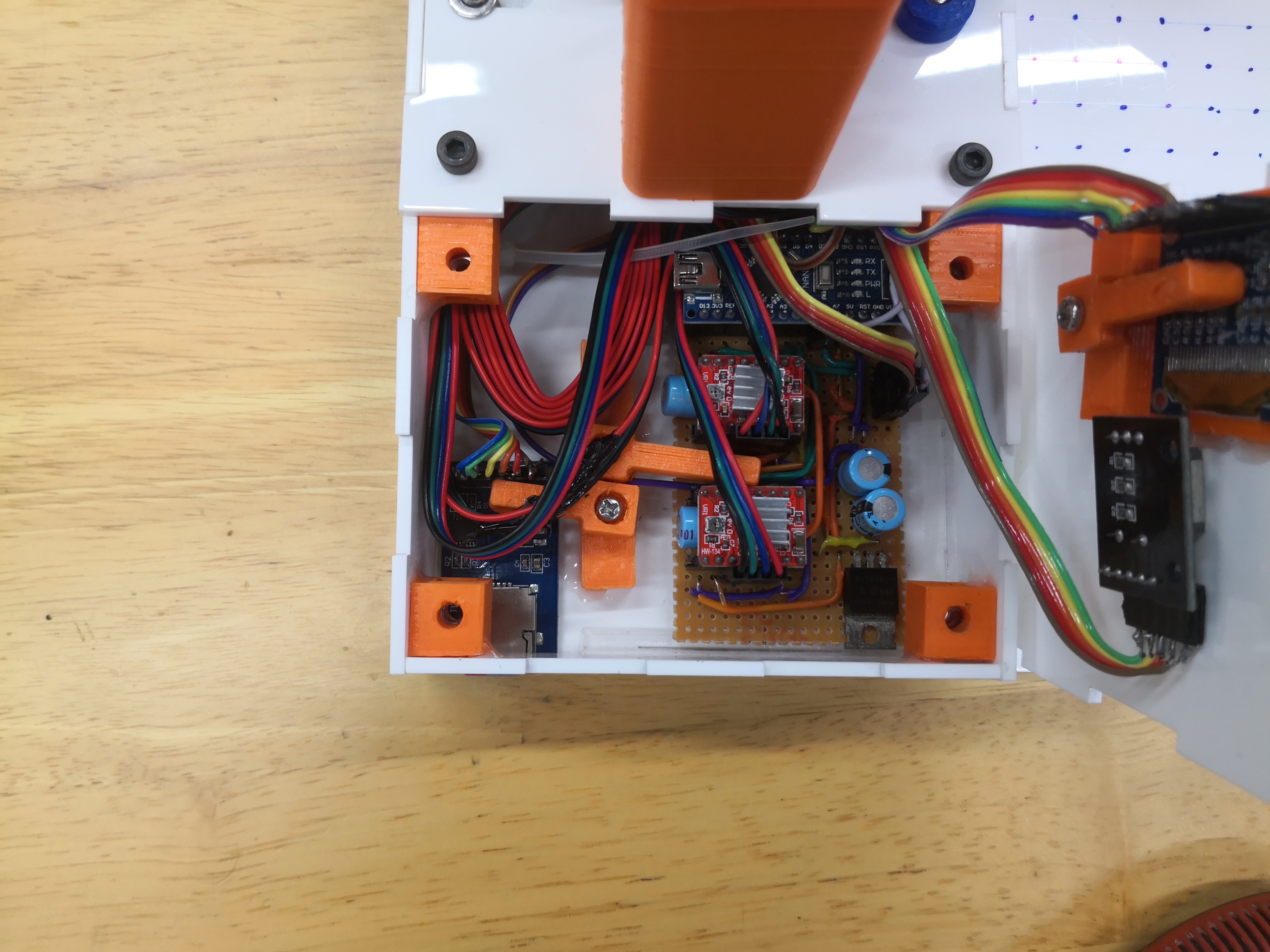
Excess wires are coiled up.
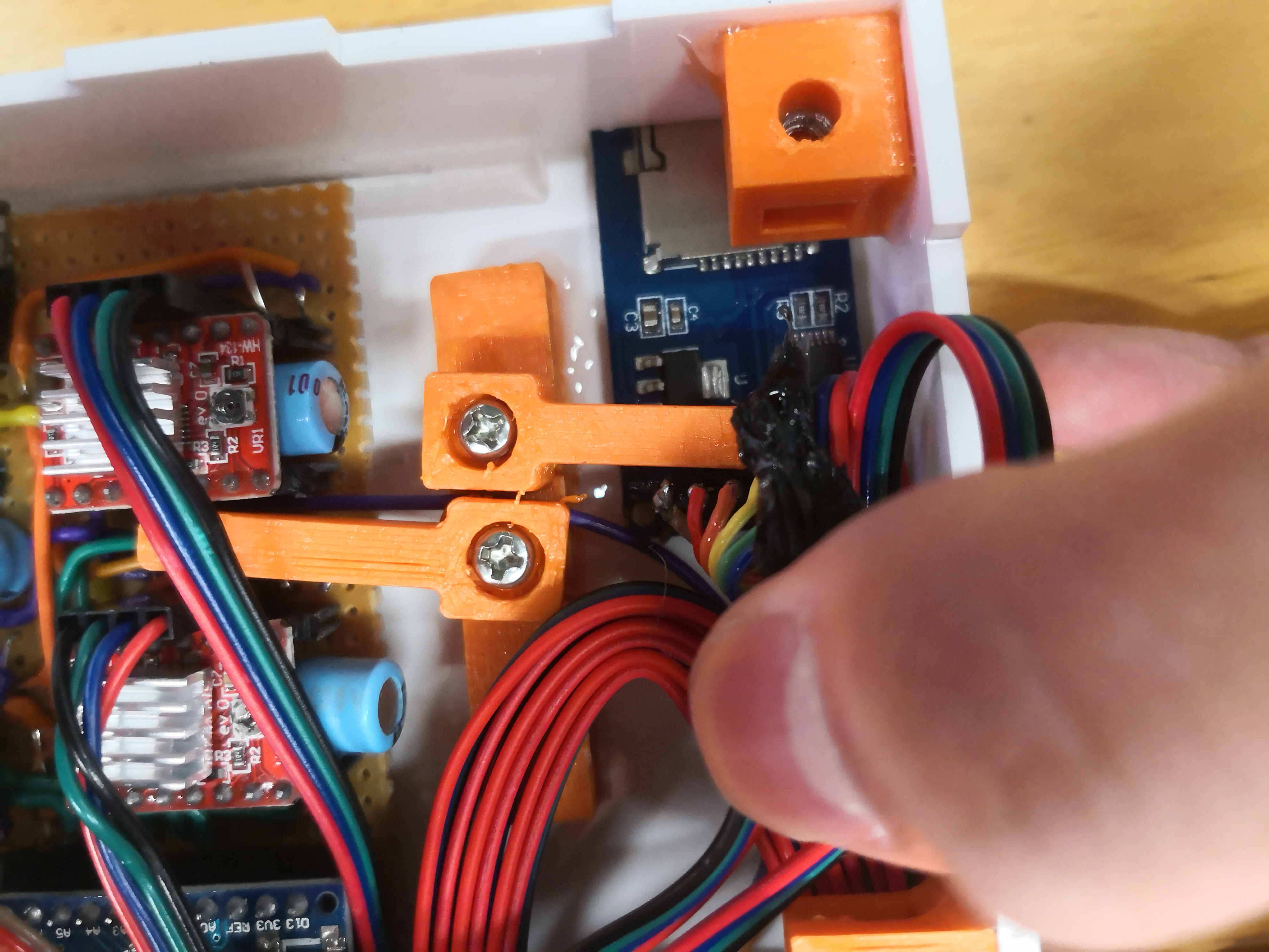
Sufficient length is left to open the box for maintenance.
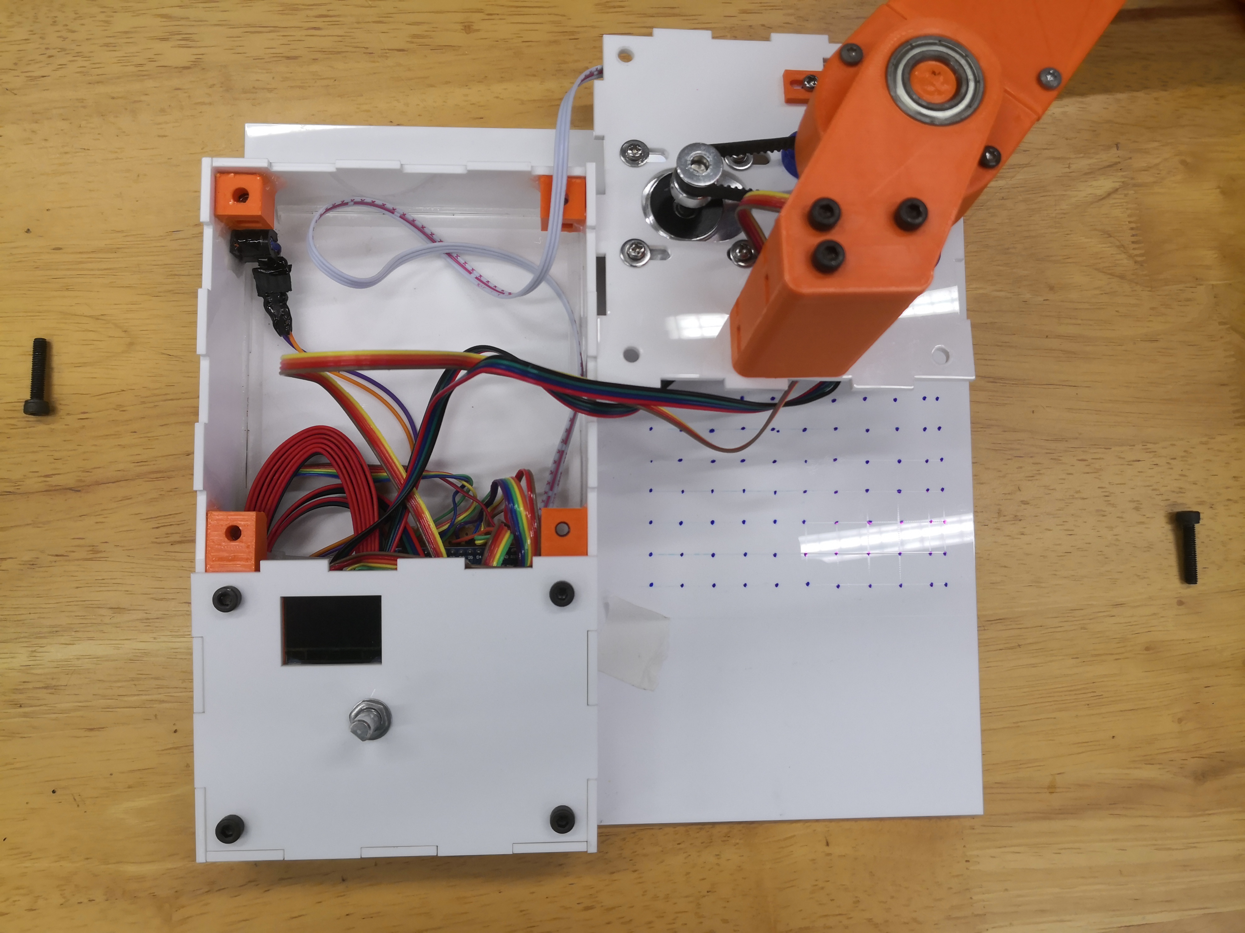
Servo wiring for the arm.
Final prototype-Testing
First plot
Below is the first thing drawn by the pen plotter on the bare plastic of the pen plotter.
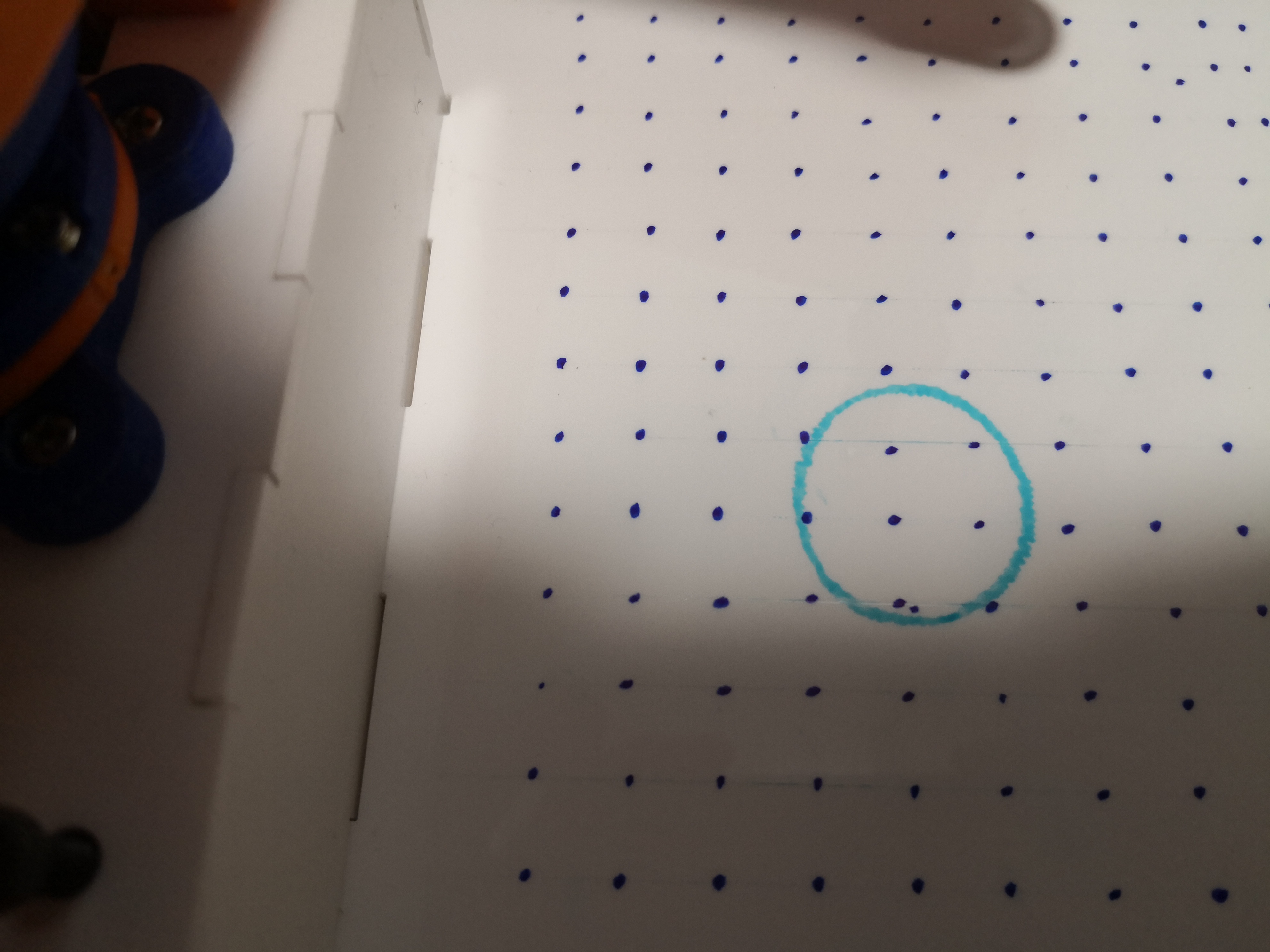
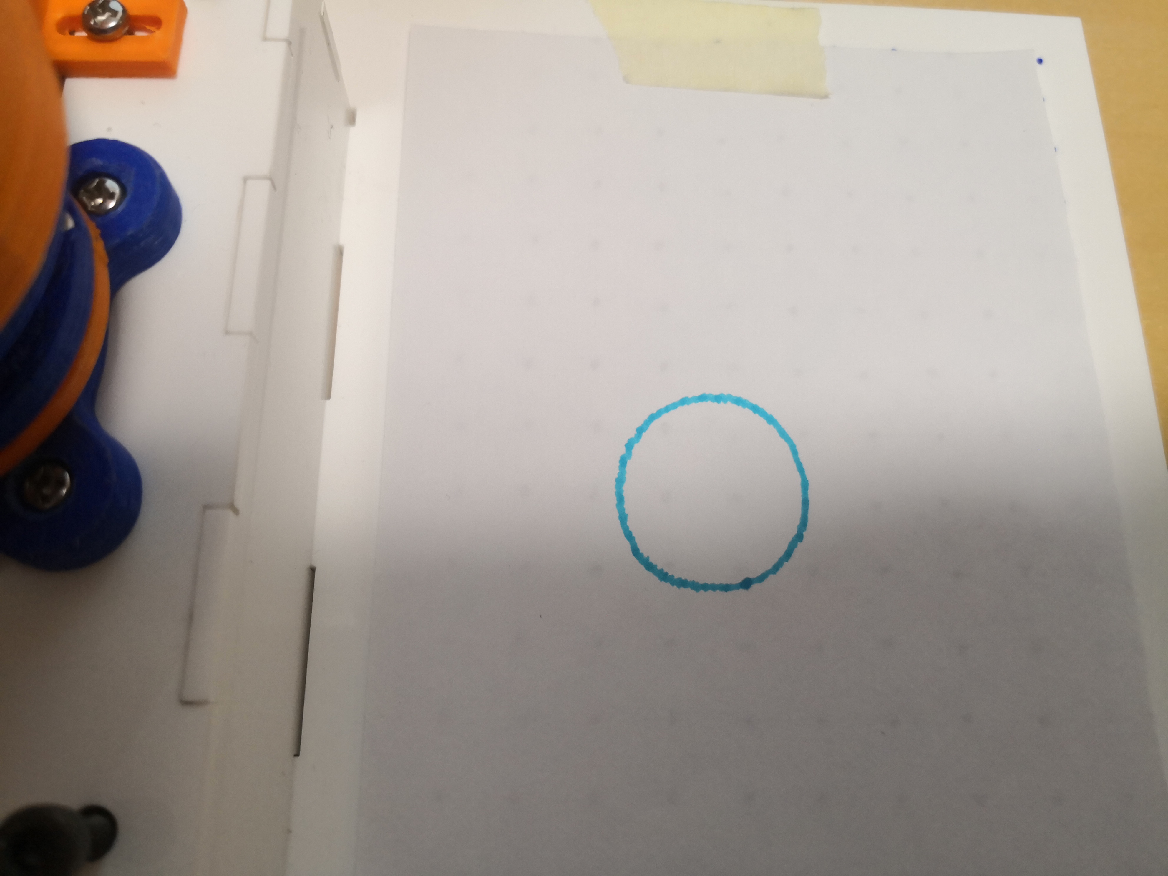
Drawing the circle again on a sheet of paper this time. The resultant circle is slightly elipticle most likely because of backlash.
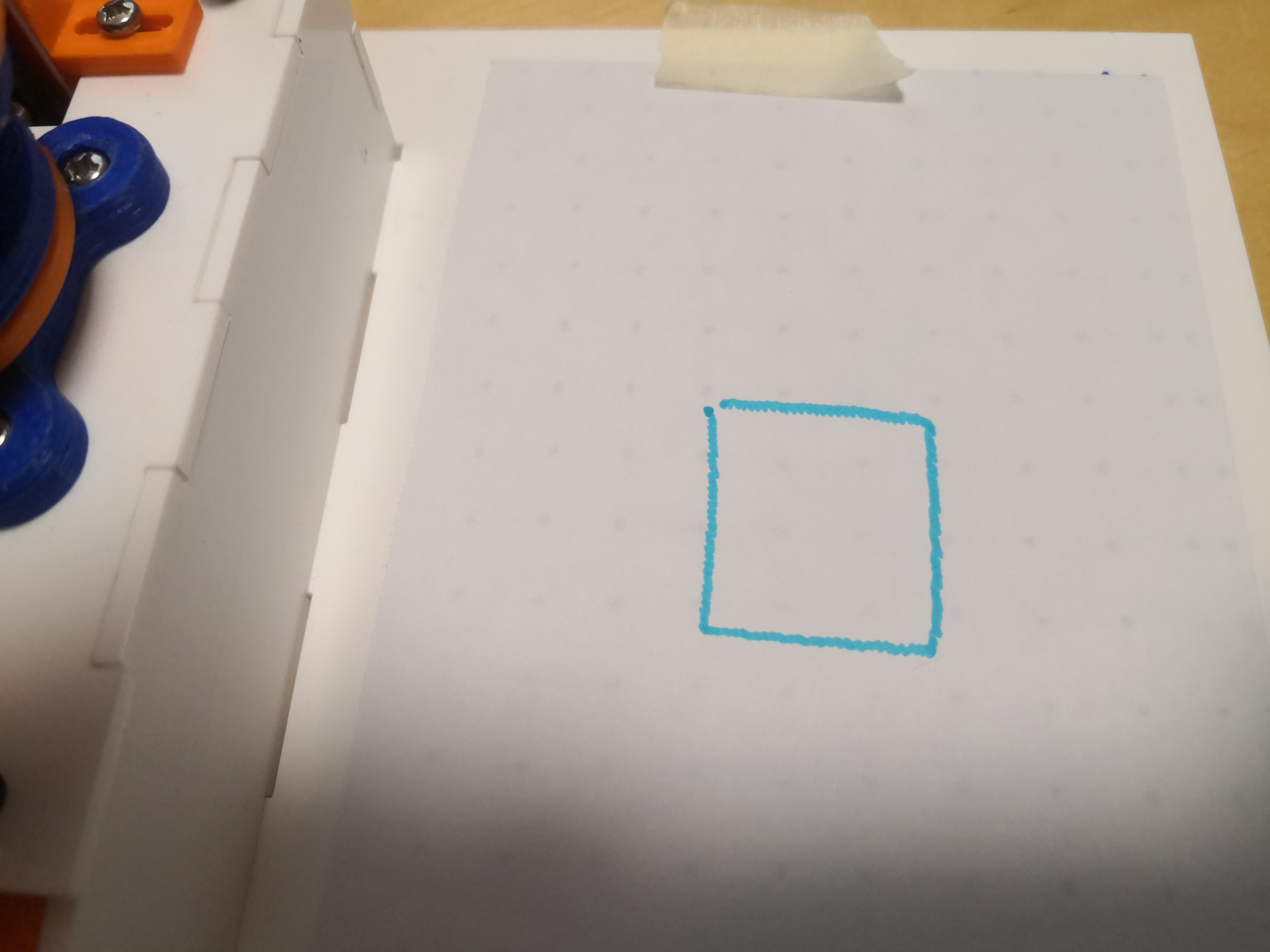
The next thing dwawn was a square. A square was what the first prototype plotter attempted to draw.
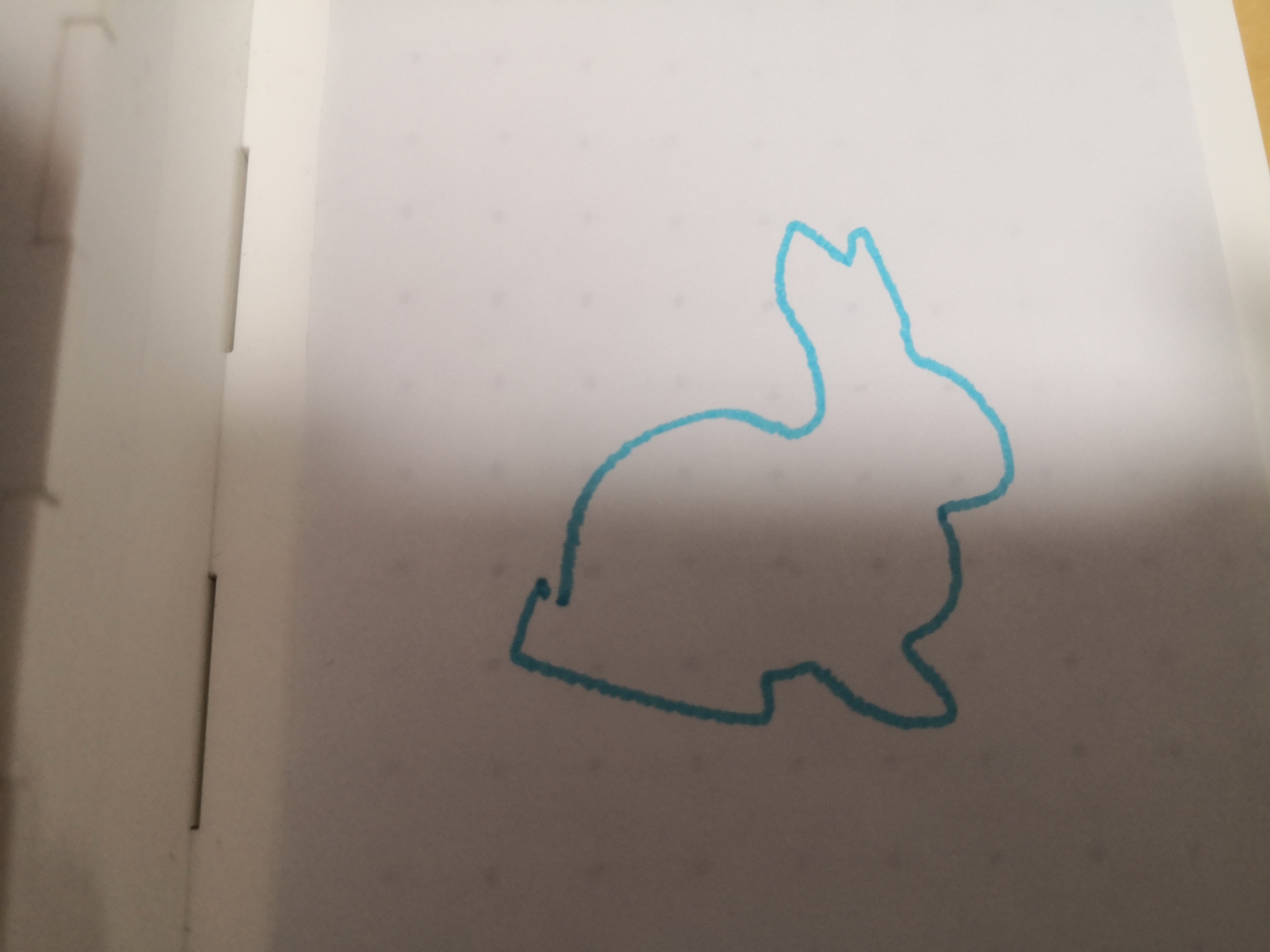
Rabbit.
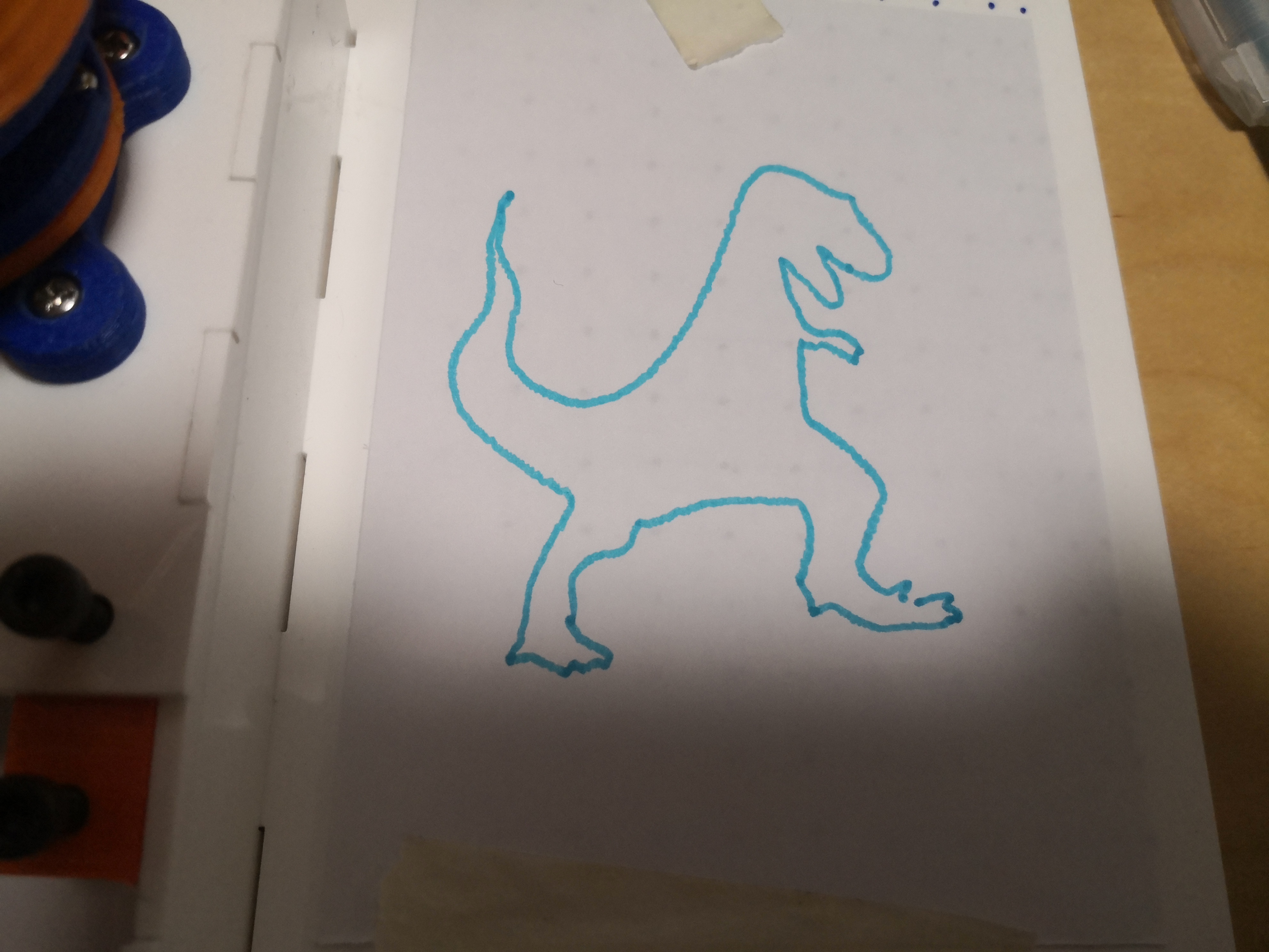
T-Rex.
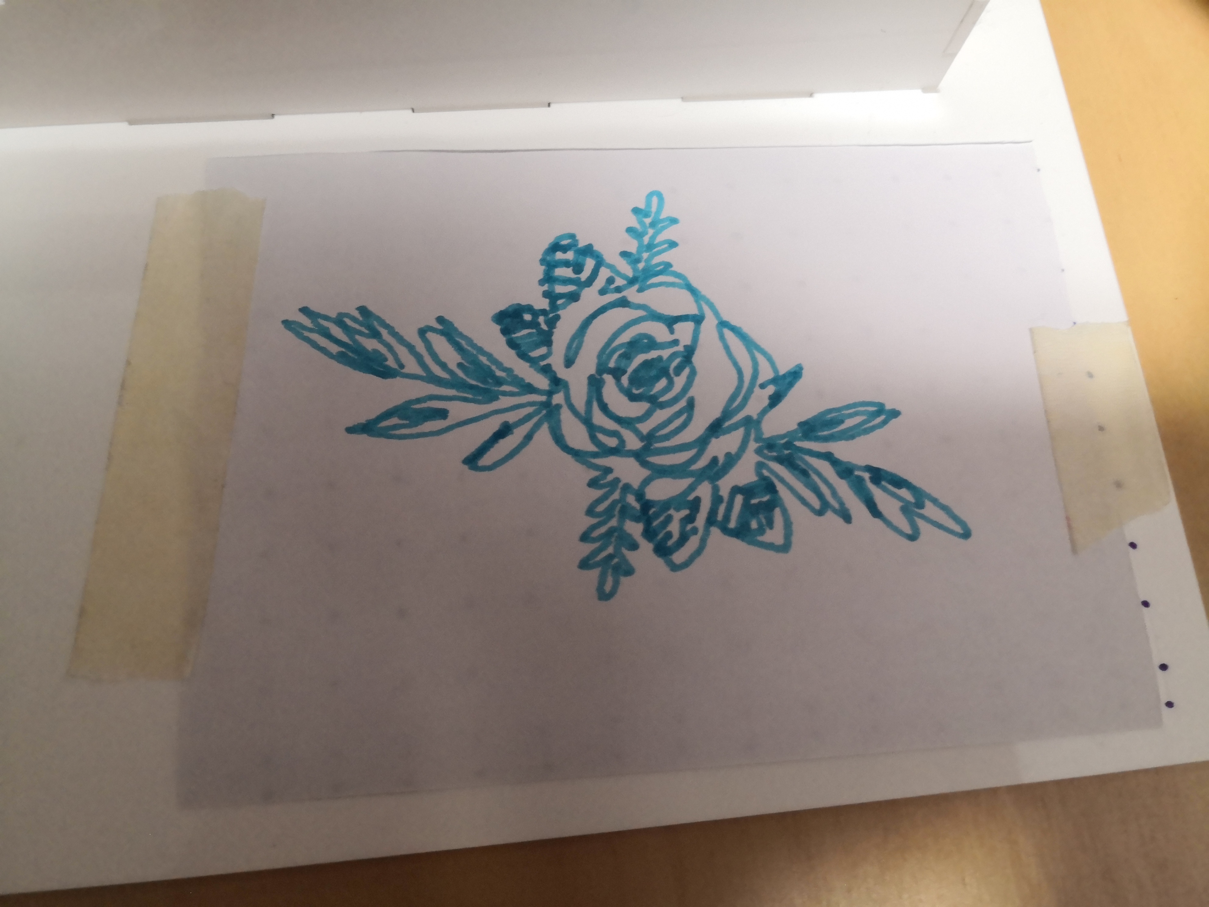
Flowers.
Standing rabbit.

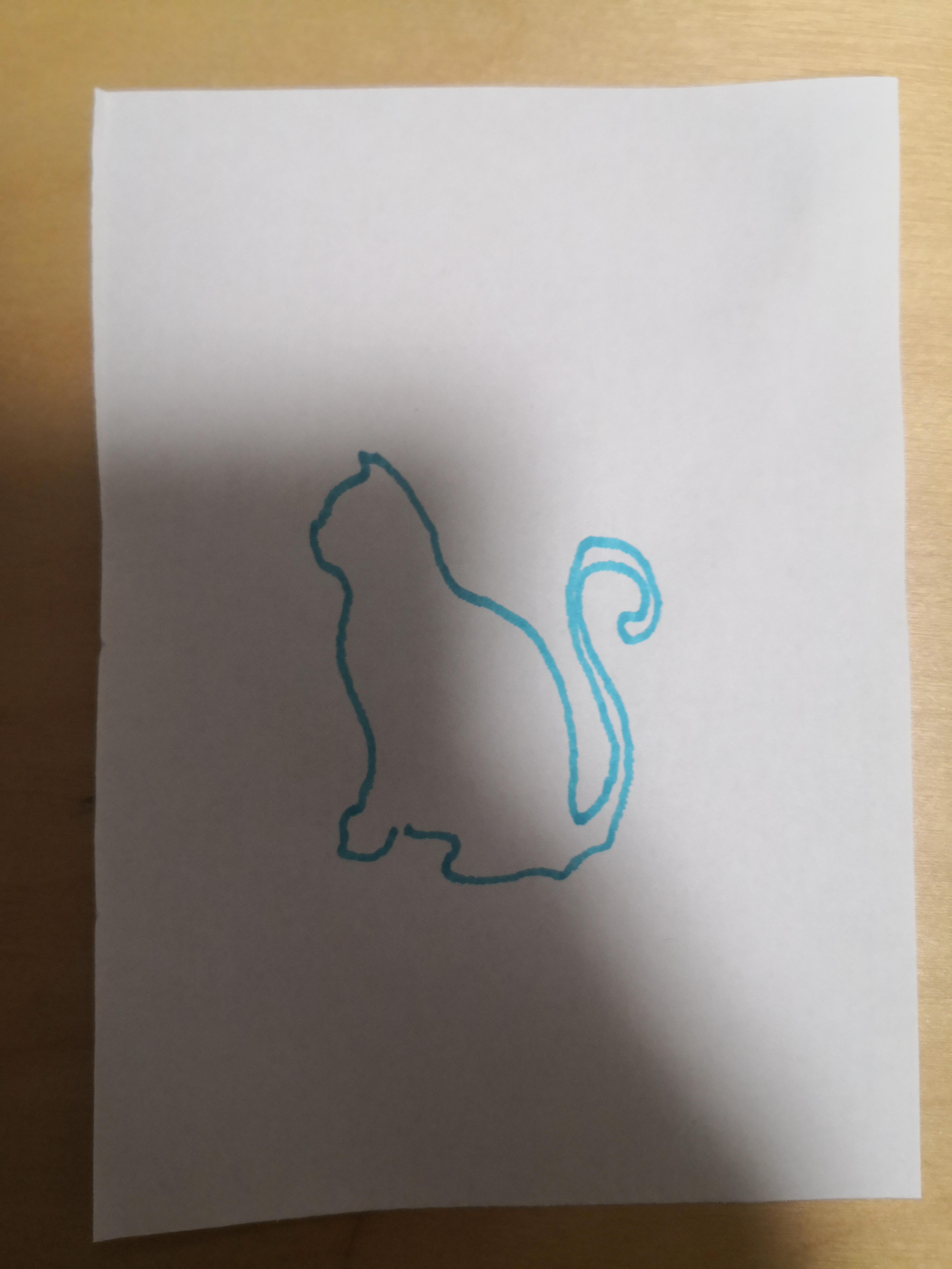
Cat.
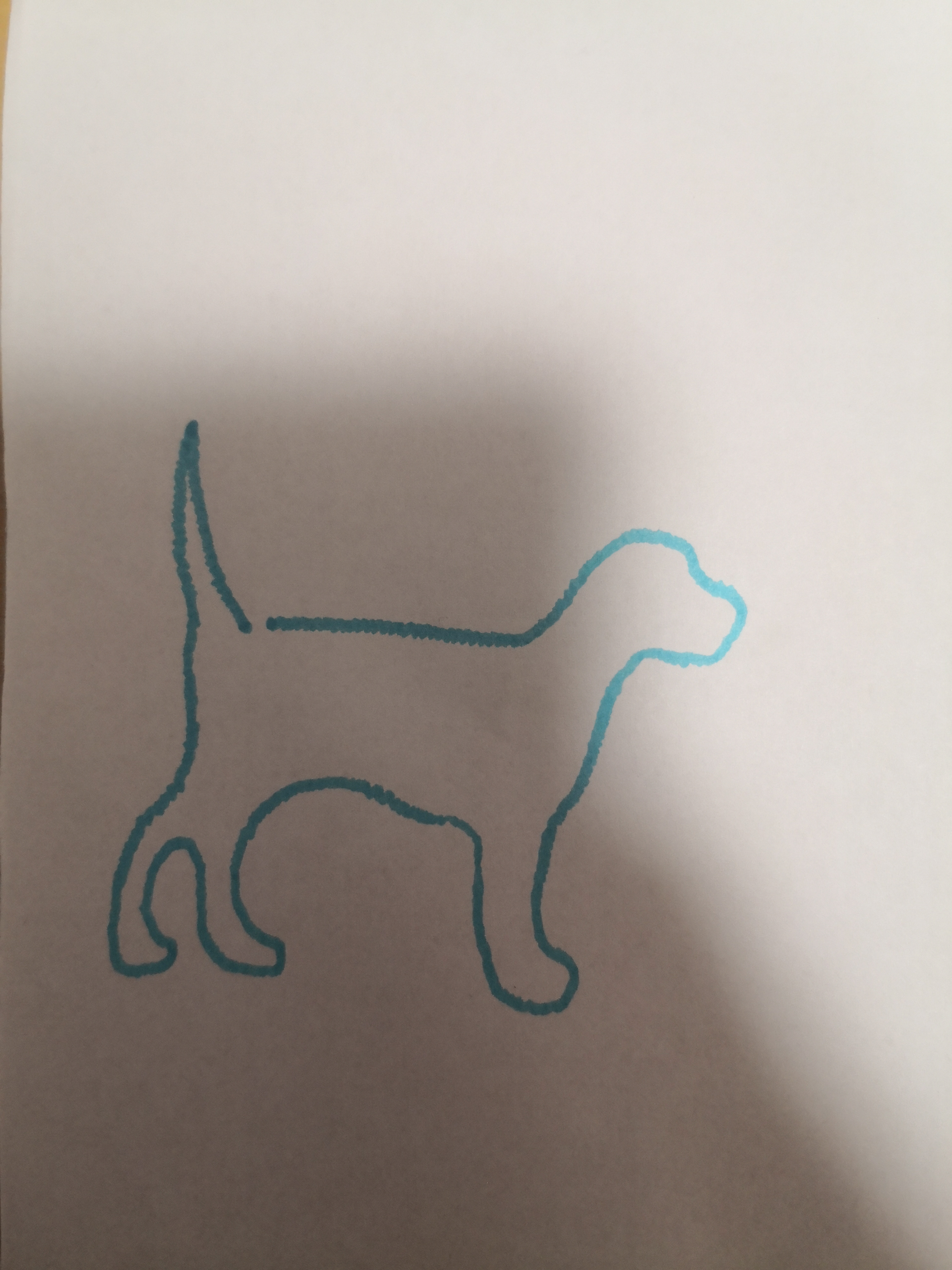
Dog.
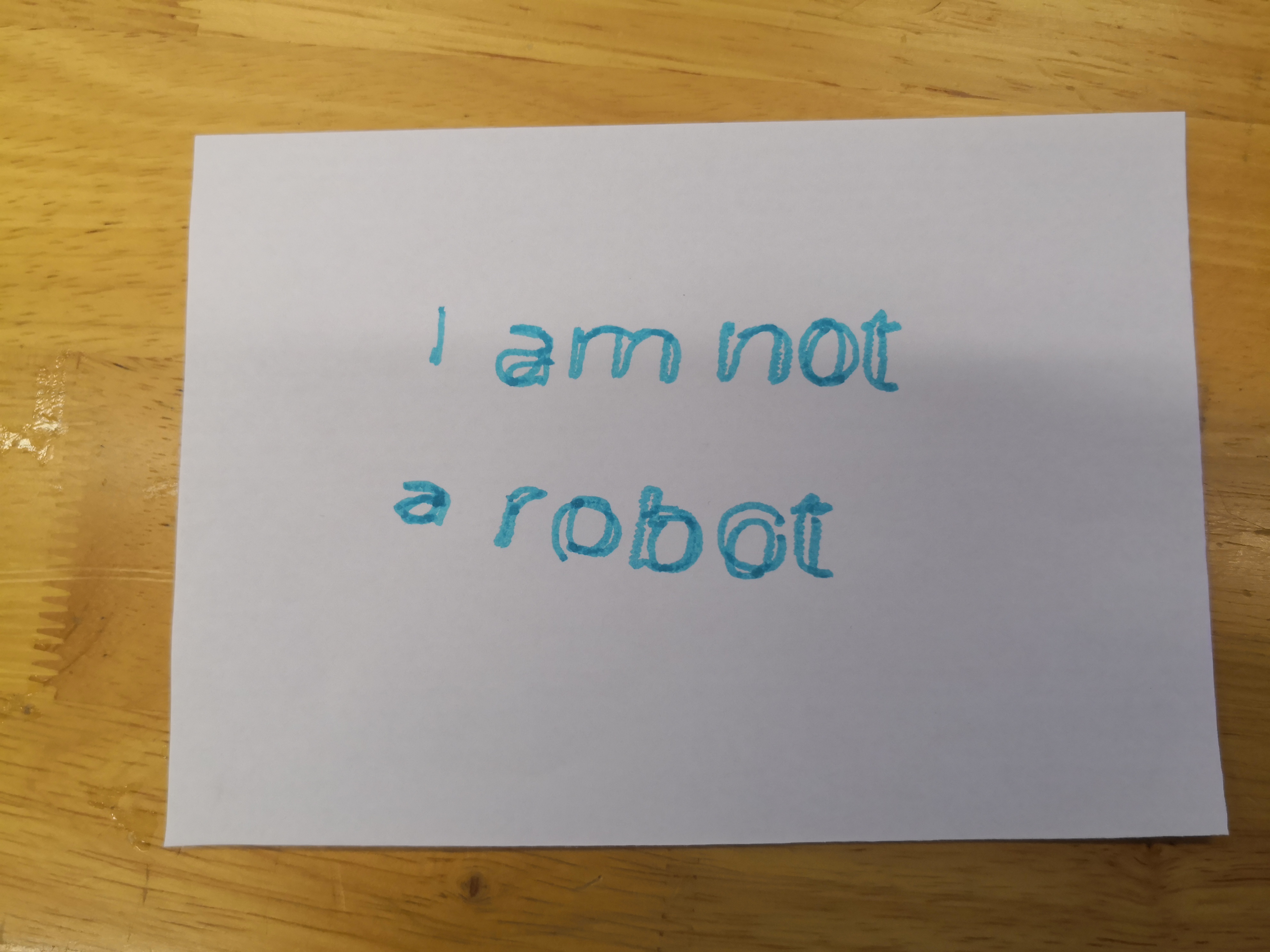
Some text drawn by the plotter. The text looks rough because of backlash.
Dinosaur.
Another cat.
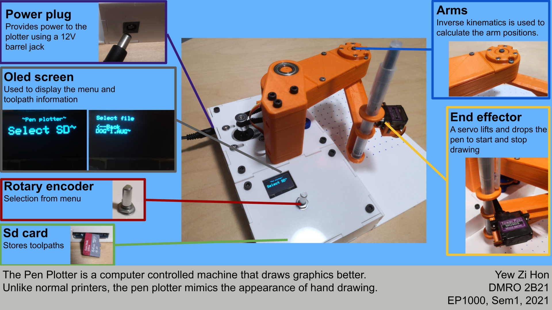
Final prototype-slide
Final prototype-video
Final prototype-How to use the pen plotter
The main steps in using the pen plotter are:
- Generating toolpath
- Mounting SD cardwith toolpath
- and Selecting toolpath
Generating toolpath
First the G-code is generated in cura, Then it is compressed by a python program.
Guide for generating a toolpath can be found here
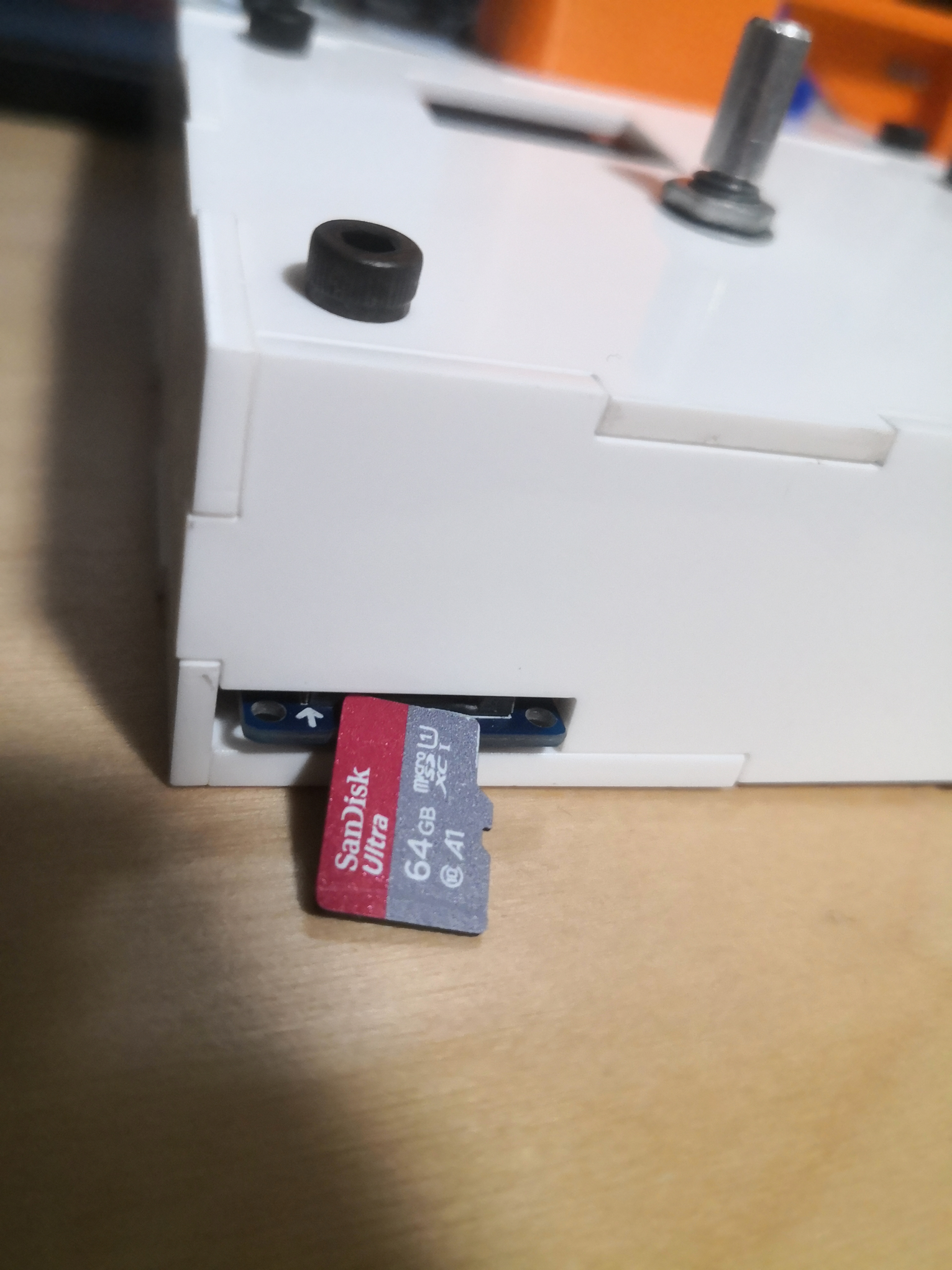
Mounting SD cardwith toolpath
The SD card must be formatted to FAT32 and have a volume 32GB or less. This can be done using built in windows utilities.
Copy the compressed G- code file to the SD card. The pen plotter can only read the first five toolpaths.
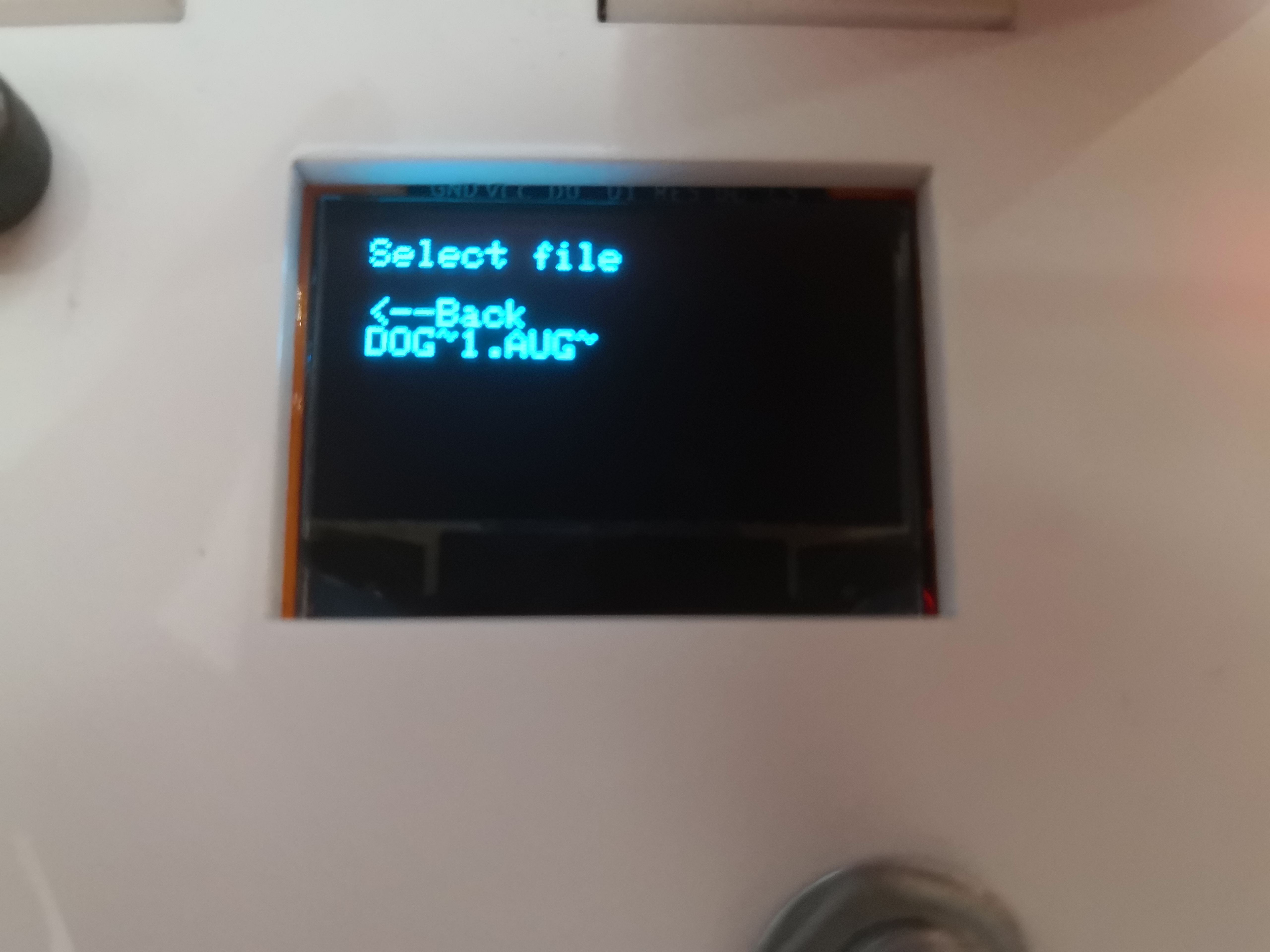
Selecting toolpath
Once the SD card is inserted, the pen plotter will list the avalable toolpaths. Select the toolpathh by turning the rotory encoder.
Final prototype-Possible improvements
Backlash
Although the backlash is lesser than the second prototype, there is still some backlash. This can be seen in the below photo. The start and end point are not the same.
Inaccurate motion
Linear interpolation is done in steps of 1mm this, can be decreased to make the motion more accurate.
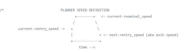
Movement planning
CNC controllers like GRBL will plan movements in advance and create a buffer so that the velocity and acelleration of the arms will change slowly to avoid jerky motion and maintain a high accuracy.
Lack of accelleration control
There is no accelleration when driving the stepper motors and leads to jerky motion. The speed is also has to be kept low to avoid skipped steps.
Faulty rotory encoder
Some pulses of the rotory encoder could not be read as a logic high by the microcontroller, making the selection sometimes unpredictable unless the rotory encoder is turned slowly.
Unoptimised program
digitalWrite() was used in the program but the function has a relatively long execution time and port manipulation would have been faster. Using timer interupts instead of delay would also have allowed the microcontroller to perform other tasks while in the delay.
Low accuracy of plotter
The plotter has a theoratial maximum accuracy of 0.3mm when the arms are fully extended. This is assuming that the mechanical cnstruction is ridgid enough. The low accuracy is because of the low microstepping capability of the stepper drivers used. The HR4988 stepper driver acheived 1/8 microstepping, while another stepper driver, the DRV8825 can aceive 1/32 microstepping, foure times the theoratical accuracy of the HR4988.
Limited toolpaths shown
The plotter can only read the first five files in the SD card. Strings are used to store the toolpath names and since the string class dynamically assigns memory, using memory inefficiently. This is a problem because a large porpotion of memory is already used for the SD card and OLED screen, one quarter and one sixth of the memory respectively. The current program only leaves about 800 bytes for functions that allow the pen plotter to plot.
Thank you for reading! 😃